Introduction
A while back we heard about the nifty Nikon Coolpix S1000pj, a digital camera with a built-in projector. We were very curious how Nikon packaged everything into this little device, so we decided to do what we do best -- tear it apart!
Check out our YouTube video of the teardown. We included a quick explanation of the projector's inner workings right around the 2:00 minute mark!
What you need
-
-
Contents of the box include:
-
Separate instruction manuals/quick start guides in both English and Spanish. No instructions for you, French Canadians.
-
Battery Charger.
-
A/V and USB Cables.
-
Carrying Strap.
-
Nikon Software Suite Disk.
-
Nikon Remote, model ML-L4.
-
The remote even allows you to zoom and activate the shutter from a distance.
-
-
-
The extremely simple yet nifty injection molded plastic stand tilts the camera back a few degrees to allow for projection on vertical surfaces.
-
The S1000pj sports a single lamp/single LCD panel projection system to view images in a dimly-lit room.
-
The image size can vary from approximately 5 to 40 inches.
-
According to the user manual specifications, the output resolution of the projector is VGA equivalent.
-
-
-
We here at iFixit strongly support the work the Rebel Alliance is doing to Restore the Republic and we fully stand behind their cause.
-
"Help me Obi Wan Kenobi, you're my only hope."
-
It's a shame the S1000pj doesn't beep or whistle or stop garbage compactors from crushing future Jedi knights.
-
-
-
The dimensions of the camera are 99.5 x 62.5 x 23 mm (4 x 2.5 x 0.9 in), and it weighs in at approximately 155g (5.5 oz.) without the battery and SD memory card.
-
Hidden behind the lens cover in the upper right corner is the Nikkor 5X wide optical zoom VR 5.0-25.0 mm 1:3.9-5.8 lens.
-
The back panel houses the comparatively large 2.7-inch High Resolution Bright LCD.
-
The slider on the third picture (boxed in red) focuses images projected from the front of the camera.
-
-
-
-
A few more screws secure the rear case to the body.
-
After prying around its perimeter, we lift the rear case off the body.
-
Surprisingly, both the front and rear outer cases are machined out of aluminum.
-
The button covers attach to the rear case while the electronic portion is attached to the metal shield next to the display.
-
-
-
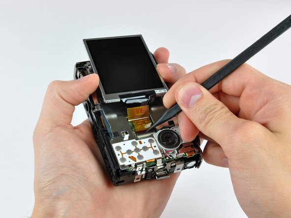
The display is attached to the metal shield by several fingers that apply pressure between the shield and the edge of the display.
-
Flip back the ZIF cable lock and remove the display.
-
Use a plastic opening tool to pop the speaker assembly out of the metal shield.
-
The speaker pumps out some pretty fresh beats when the camera is in projector mode.
-
-
-
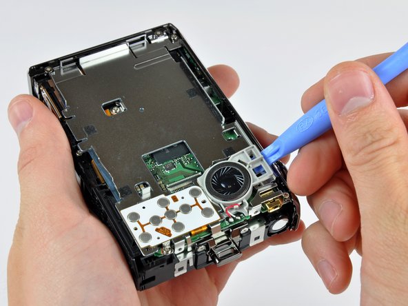
Remove a few screws around the perimeter of the open back of the camera.
-
After some (careful) prying, the top and right covers pop right off.
-
Interestingly, the controls along the top of the camera are attached to a board below the top cover. The top cover just houses the button covers.
-
-
-
The camera module in all its glory.
-
Like most compact digital cameras with optical zoom that have no externally telescopic lenses, the S1000pj's internal zoom lenses move perpendicular to the front face.
-
The basic components include:
-
A few movable lenses.
-
CCD image sensor.
-
Optical zoom motor and feedback sensor to position the lenses.
-
Aperture and image stabilization modules.
-
Light has to travel through at least four glass lenses until it shines on the CCD sensor. What a journey.
-
-
-
We had to disconnect a few additional ZIF cables and remove some screws still securing the the logic board to the main chassis.
-
Disassembling this camera is not for the faint of heart -- Nikon definitely did not intend this device to be user serviceable.
-
We even had to de-solder a bunch of components including the camera cover actuator, projector LED, and flash bulb.
-
-
-
Here's an inside look at the projector assembly sans the protective cover.
-
Light for projecting images is supplied by a very powerful LED (shown in red) that even has its own heat sink to conduct heat to the aluminum front panel.
-
As light leaves the LED it passes through some filters and lenses (shown in orange).
-
A good deal of engineered optical reflection allows the light emitted by the LED to reflect through a tiny LCD panel (shown in yellow) and head toward the mirror.
-
Before bouncing off the angled mirror and exiting the camera, the projected image passes through a focusing lens (shown in blue) connected to the slider on the top panel.
-