Introduction
The main thing that usually breaks on a jump starter is the battery. These units usually contain a lead acid battery with a finite lifespan. It is possible and simple to replace but usually not financially worth doing. If the unit does not hold a charge but functions while it is plugged in then it is most likely a faulty battery.
What you need
-
-
Power Station Jump Starter
-
Model PS1100
-
The bad battery could be replaced to restore it to full functionality.
-
-
-
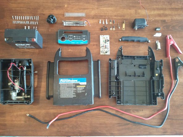
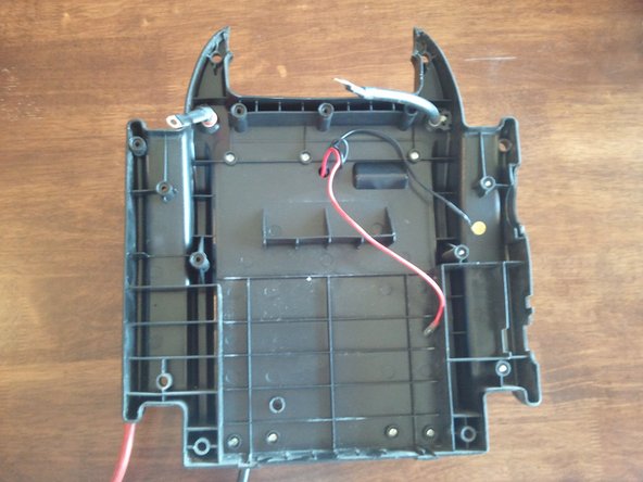
Opening it up reveals the Lead battery, AC/DC converter, 12V DC input, switch, back of circuit board, back of light.
-
Additional bells and whistles are sometimes added (lights, switches, compressors, power jacks, etc.) Some have AC power jacks which require a DC/AC converter which is more expensive than an AD/DC converter.
-
-
-
-
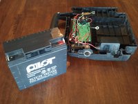
The battery to the left is the culprit of the dead power supply. A jump starter is nothing more than a small car battery with some wires.
-
Any 12V battery with the same dimensions should work as a replacement
-
This is a Lead 12V 17AmpHours battery made by Pilot battery Co. Ltd.
-
Model PL17-12
-
-
-
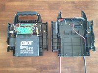
Both power inputs. AC/DC converter and DC 12V input.
-
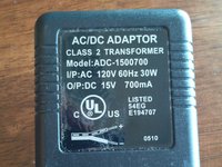
The designers of this jump starter simply purchased an aftermarket AC/DC adapter and built it in.
-
The adapter has an input of 120V (typical outlet voltage) and an output of 15V (perfect for charging a 12V battery).
-
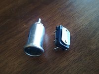
Left - DC Power Jack, Right - Thermal Relay for safety and protection
-
-
-
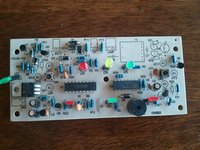
Circuit board with your typical LEDs, Resistors, Transistors (black half circles), IC chips (long black), Capacitors (disks and cyliders), buttons (right middle) Power Rectifier (left middle square), Diodes (small black, bar on one side), Piezo Speaker (large and round, bottom)
-
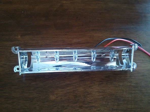
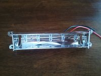
Light with 5 LED's
-
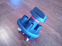
Big Switch to handle 12V
-
-
-
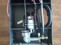
The back module is the compressor. It will still function normally by application of a 12v power supply.
-
I did not disassemble the compressor. I will bolt a plexiglass cover over the top and solder a 12v car adapter to run it as an emergency compressor
-
I have a walk through on recycling the compressor on instructables.com
-


27 Guide Comments
I have one of these that the ac adapter has come loose from the main board. is there a possibility that you could post a photo of exactly where the adapter solders onto the main board?
To charge the battery? The back of the unit will say what the "input" should be.
helpful article any chance on getting the dimension of the battery I do not see PL17-12 but many like it. the dimension would be helpful