Introduction
The electricity meter is one device that no household connected to the grid can escape, and the technology utilized by analog meters (the most common type) dates to the late 19th century. However, engineers have recently developed a solid state electronic meter that sends electricity consumption readings wirelessly. This new meter eliminates human error and allows utility companies to monitor their systems more accurately.
We were always interested in these meters, but had trouble acquiring one for a teardown -- it's not like you can just walk into a Best Buy and pick one off the shelf. Thankfully, the generous folks over at Elster were kind enough to send us one of their REX2 meters for thorough dissection!
The controversy surrounding the implementation of smart meters prompted us to take a close look at their hardware to see what exactly makes these devices tick.
What you need
-
-
Introducing the energy meter of the future: the Elster REX2 Watthour meter.
-
The REX2 meter provides several enhancements over non-programmable meters:
-
Nonvolatile memory rated for 1,000,000 write cycles
-
Advanced security with full 128-bit AES encryption
-
Remote upgradeability
-
Support for 900 MHz and 2.4 GHz ZigBee communication
-
Optional: flux capacitor add-on???
-
-
-
Our Elster REX2 smart meter is labeled as Type R2S. The 2S model has an operating voltage rating of 240 V ranging from 192 V to 288 V at a nominal frequency of 60 Hz.
-
Elster's meters operate on 25 channels across the 902-928 MHz ISM band using a controlled path mesh.
-
If a specific household has concerns about their meter being used as a repeater, they can contact their utility company to request that their Elster meter transmits power readings just once a day.
-
-
-
-
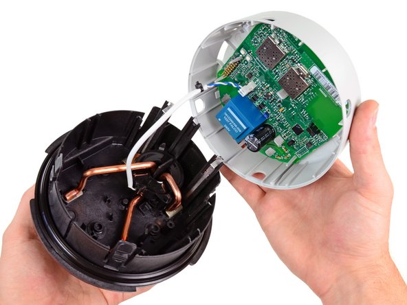
After disconnecting a single cable, we get a good look at the smart meter's power connections.
-
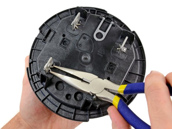
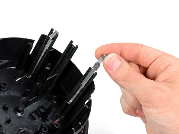
The retaining clips holding the power connections to the back of the rear case are easily removed using our large needle-nose pliers.
-
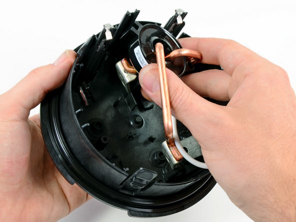
After a bit of wiggling, the power connections come out with little resistance.
-
-
-
Extremely thick copper wires allow the meter to be wired in series with a household's main power supply. They're capable of handling 200 Amps!
-
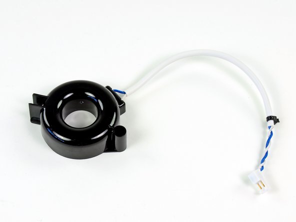
Interestingly, the meter relies on a black ring-shaped current transformer installed around the copper wires to send power consumption signals to the main board.
-
Long metal pressure contacts along the inside case of the meter conduct 240V AC electricity to pads that provide power to the main board.
-
-
-
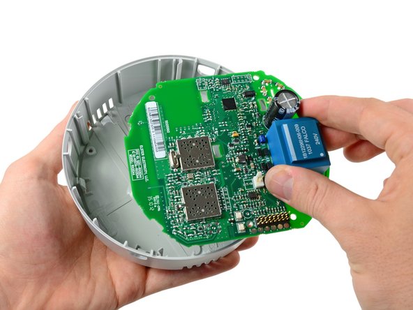
Main IC's located on the front side of the motherboard include:
-
Teridian 71M6531F SoC with an MPU core, RTC, FLASH and LCD driver
-
Texas Instruments LM2904 low power dual operational amplifier
-
RMFD RF2172 medium-power high efficiency amplifier IC
-
Texas Instruments CC1110F32 Sub-1GHz System-on-Chip with MCU and 32kB Flash memory
-
Two pads near the top of the board channel 240V AC electricity from the large copper wires onto the board and into the adjacent blue transformer box that steps it down to about 10V AC. From there, the AC voltage is rectified and conditioned to power the DC components on the board.
-
-
-
The true innovation in the smart meters is their ability to relay power consumption statistics without direct contact from a meter reader. Our Elster meter accomplishes this by sending encrypted signals on the 900 MHz ISM band. The antenna can be seen on the rear side of the board near its bottom edge.
-
Elster meters only relay information when they are spoken to by other meters in the mesh. When they relay information the amount of RF radiation emitted is ~1/4 W, which is less than most cellular phones.
-
-
-
The controversy surrounding smart meters is the question of whether the additional radio-frequency (RF) signals will cause any undesired health effects.
-
On one side of the coin, as petitioners have pointed out, smart meters contribute to the already looming cloud of "electro-smog" produced by the multitude of today's devices that produce RF signals.
-
On the other hand, it seems that opponents do not consider the claimed operational characteristics of smart meters. As PG&E points out (they use meters manufactured by GE):
-
Consider that SmartMeters™ transmit only about 45 seconds a day. You'd have to have one of our meters on your home or business for more than 1,000 years to get as much exposure to radio waves as a typical cell phone user gets in just one month.
-
So if the device was always on, 24/7, there might be a cause for concern. But if what PG&E states about the limited transmit time is true, your cellphones, Wi-Fi internet, and microwaves are probably causing your body more damage than a smart meter would. That is, unless you've never used a cellphone or any other device producing radio frequencies.
-
-
-
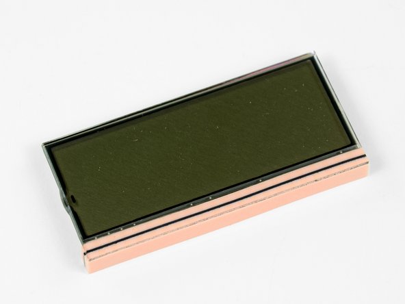
Lastly, we can remove the LCD.
-
As you can see, the monochrome LCD does not have any ribbon cables connecting it to the motherboard.
-
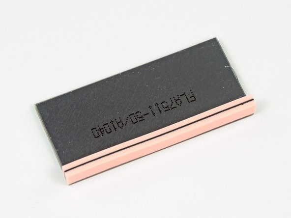
It seems to work via a method of conduction, where the bottom black strip comes into contact with pads on the motherboard, thus producing an image.
-
This method of LCD connection is very common, and the black and pink strip is called a "zebra connector."
-
-
-
Normally we'd assign a Repairability Score on the last step, but we don't feel it's appropriate for this device. After all, there's a tamper-evident security seal for a reason.
-
Even so, we're glad to know that the smart meter doesn't have easily-breakable internal components, and can be serviced without difficulty by an authorized service technician.
-
A big thanks to Elster for providing us one of these meters! We certainly didn't want to take ours off the grid in order to mess around with it.
-


11 Comments
The LCD connector is a commonly used "zebra strip". Multiple parallel (for redundancy)conductive paths in the strip carry the signal to each pad of the LCD glass substrate. These pads are are generally quite transparent. The connections to the display are self-aligning and the zebra strip provides cushioning for the LCD as well.
You state: "So if the device was always on, 24/7, there might be a cause for concern. But if what PG&E states about the limited transmit time is true, your cellphones, Wi-Fi internet, and microwaves are probably causing your body more damage than a smart meter would."
According to PG&E, a Smart Meter transmits on average meter about 45 seconds per day, but could be as high as 14 minutes (875 seconds) per day.. This transmission occurs all throughout the day and night averaging 2 seconds per hour.
But that only tells half of the story.
According to PG&E, there are on average about 10,000 transmission per day (about 7 times per minute) and up to 190,000 times per day (about 132 times per minute). http://blog.sfgate.com/energy/2011/11/03...
The continuous pulsed signals are well-documented in online youtube videos.
This is like getting hit in the head by a sledge hammer once every 8 minutes. Yes, this is cause for concern.
There is no SURGE protection no this beast!
Now let me think!
The Great Technological innovation, is powered by 240VAC, straight off the the power grid, which is susceptible to "Surges" when Lightning activity is taking place in the neighborhood, and transients generated from power outrages being restored, and I see no visible surge protection for the delicate circuitry on the motherboard, or elsewhere in the parts breakdown.
In addition power and signals for the motherboard circuitry is shuttled around by pressure contacts and "Zebra" connectors in an environment exposed to to the temperatures and humidity of the OUTDOORS environment.
Is this some kind of a mystical device, like the "Flux capacitor" of the back in the future slapstick comedy?
Or is it more likely the Elster folks are jesting with the Ignorance of the general public?
Honestly!
Let me ask the question?
What is the MTBF of this toy?
Thirty Seconds after Installation to fire conflagration?
and sixty seconds to errant metering data? Whichever comes first!
I have seen Christmas toys designed better that this abomination of Electronic design Principles.
http://www.forbes.com/sites/williampentl...
5/03/2011 - Not-So-Smart Meters Overbilling Californians
Scores of consumers in California paid for more electricity than they actually used due to errors made by about 1,600 flawed “smart meters” installed by a major investor-owned utility. Ironically, the same “smart meters” were at least partially paid for by California rate-payers with the expectation that the meters would reduce the price paid by end-users for electric power. I suspect the affected customers do not find the irony amusing.
The utility, Pacific Gas and Electric Company, admitted yesterday that about 1,600 so-called “smart meters” had charged customers for phantom power. The meters, manufactured by Landis+Gyr, malfunctioned when they get too hot...
The PGE meters don't transmit only 45 sec per day That is an average.
From WirelessMess.org (and this same info can be found in the Administrative Law Judge's transcript of the hearing): When they say the meter only emits “45 seconds per day” they don’t tell you that means 15,000 pulses.
To record these increments data is transmitted multiple times, every minute, 24 hours a day. If you ask PG&E they will most likely tell you that data is only transmitted six times a day. However PG&E was forced to admit to Administrative Law Judge Yip-Kikugawa that their meters were much stronger than advertised to the public, and each electrical meter puts out bursts of microwave radiation from 9,600 to 190,000 times a day.
The electric meters operate continuously, sending out quick bursts of radiation lasting milliseconds. Considering these bursts are sent out several times a minute, they add up to thousands of bursts all day long.
Utilities use time-averaging to report the meters' power.