Introduction
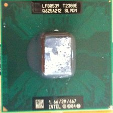
The Dell latitude D620 was introduced in March 2006. Both the first MacBook Pro and this Dell Latitude D620 have the same Intel Core Duo T2300E. Like the first MacBook, they both have Intel's GMA 950 Integrated Graphics.
What you need
-
-
Open the laptop's screen 180 Degrees so it is straight back.
-
Use a flat head screwdriver or a spudger to pry the top bezel off. Work it side to side until the bezel is freed from the chassis, exposing 3 screws
-
-
-
Use your fingers to carefully lift up the keyboard. Refer to the first picture for guidance.
-
Carefully pull the keyboard upwards toward the LCD screen so it can be released from the bottom tabs.
-
Carefully lift the keyboard so the keys are resting on the palmrest, this will expose the ribbons for the keyboard, trackpad and Tracking Nub.
-
-
-
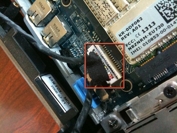
First insert a small flat head screwdriver or a spudger into the small notch in between holding down the ribbon.
-
Then grab the metal bar on top of the keyboard connector and pull straight up. The cable should come free.
-
-
-
Grab the top of the display connector and pull it straight up and out.
-
-
-
Use a tool or your fingers to gently remove the antenna cables from the wireless card.
-
-
-
-
Pull back the clips by the antenna connectors, and the card should rise up on its own. Gently remove the card from its socket.
-
-
-
Using similar procedures as the WLAN, disconnect the single antenna cable, push the rear clips back and remove the card.
-
-
-
Close the laptop screen completely, make sure it clips in place.
-
The bottom screw is labeled with D, remove it.
-
The screw on the rear is not labeled, remove it as well.
-
-
-
Pull it straight up, making sure all cables are free of their routing ares.
-
-
-
Remove all of the remaining screws on the laptop with a Phillips screwdriver.
-
There are screws on the top under the keyboard as well, remove those.
-
-
-
Seperate the palmrest from the device, starting from the back by sliding it forward and pulling it most of the way off.
-
-
-
With a Phillips screwdriver, remove the 4 screws on the heatsink, in order of the numbers of the metal.
-
-
-
Grab the heatsink and remove it, it may require force.
-
There is still thermal paste and a thermal pad attached.
-
-
-
Clean the remaining thermal compound off of the CPU. Remove the thermal pad if it is still stuck to the GPU.
-


8 Comments
Seems like it would make a perfect "Hackintosh."
Quote from Chris Green:
Seems like it would make a perfect "Hackintosh."
Yes. It does indeed. I've been using it as a hackintosh sense early February. I had Mac OSX 10.6.2 on it, even before I performed this tear down. I was able to use software updater to go strait from 10.6.0 to 10.6.2. Skipping 10.6.1. I've only had a few kernel panics. I've even been using the iPhone SDK. It is a very stable hackintosh. The GMA 950 can even play The SIms 3 w/o any issues.
Fantastic guide!! Thank you for taking the time and effort to create it!
There is a little flat, white, Multi-wire connector in the upper-left corner.
I suspect that this is where the optional Bluetooth module would be located, can anyone confirm this?
Thanks,
Tim D.
Yes, the flat white connector on the left side above the keyboard is for the optional bluetooth connector. It interfaces via USB.
souta95 -