Installing MacBook Pro 15" Core 2 Duo Models A1226 and A1260 LCD Panel

  • Add Note x
  • x 83

Save money by replacing just the LCD rather than the whole display assembly.

Sections
Tools
first image
thumb image 1
thumb image 2

Add Note Edit Step 1 — Battery  ¶ 

  • Use your fingers to push both battery release tabs away from the battery, and lift the battery out of the computer.

first image
thumb image 1
thumb image 2

Add Note Edit Step 2 — RAM Shield  ¶ 

  • Remove the three identical 2mm Phillips screws from the memory door.

  • Lift the memory door up enough to grip it and slide it toward you, pulling it away from the casing.

first image

Add Note Edit Step 3 — Upper Case  ¶ 

  • Remove the two 2.8 mm Phillips screws in the battery compartment near the latch.

first image

Add Note Edit Step 4  ¶ 

  • Remove the following 6 screws:

    • Two 10 mm T6 Torx screws on either side of the RAM slot.

    • Four 14.5 mm Phillips screws along the hinge.

first image

Add Note Edit Step 5  ¶ 

  • Remove the four 3.2 mm Phillips screws on the port side of the computer.

first image

Add Note Edit Step 6  ¶ 

  • Rotate the computer 90 degrees and remove the two 3.2 mm Phillips screws from the rear of the computer.

first image

Add Note Edit Step 7  ¶ 

  • Rotate the computer 90 degrees again and remove the four 3.2 mm Phillips screws from the side of the computer.

first image
thumb image 1
thumb image 2
thumb image 3

Add Note Edit Step 8  ¶ 

  • Do not yank the upper case off quickly. The case is attached to the logic board via a ribbon cable.

  • Lift up at the rear of the case and work your fingers along the sides, freeing the case as you go. Once you have freed the sides, you may need to rock the case up and down to free the front of the upper case.

  • There are four plastic clips above the DVD slot, and another above and to the left of the IR sensor. These clips can be very difficult to disengage without prying. They can also be difficult to re-engage during reassembly.

first image
thumb image 1
thumb image 2

Add Note Edit Step 9  ¶ 

  • Disconnect the trackpad and keyboard ribbon cable from the logic board, removing tape as necessary.

  • Note: It is possible to replace the hard drive without disconnecting the keyboard from the chassis, but it will need to be held upright to keep it out of the way, while still allowing you both hands to work on the drive removal. Be careful when removing the keyboard-trackpad ribbon cable to ensure that the rear of the upper case is disengaged from the area near the hinge. It is easy to accidentally bend the screw receivers on either side of the keyboard.

    • Remove the upper case.

first image

Add Note Edit Step 10 — Display Assembly  ¶ 

  • Disconnect the two or three antenna cables attached to the Airport Extreme card. Depending on your model, one of the three cables may be unused and capped with a black shrink tube.

  • Apple was kind enough to include a label showing where each color antenna cable plugs in - just make sure to look at this when reconnecting the antenna cables.

first image

Add Note Edit Step 11  ¶ 

  • Deroute the Airport antenna cables from their channel in the left speaker.

first image

Add Note Edit Step 12  ¶ 

  • Disconnect the iSight cable from the logic board by sliding the cable to the left and out of its connector.

first image

Add Note Edit Step 13  ¶ 

  • Support the display with one hand while removing the following screws:

    • One 9.5 mm silver T6 Torx screw with threads on only 3 mm of the shaft on the inside of the display hinges.

    • One 9.5 mm silver T6 Torx screw with threads on the entire shaft on the outside of the left hinge.

    • One 9.2 mm full thread T6 Torx screw securing the iSight cable ground loop to the fan.

first image

Add Note Edit Step 14  ¶ 

  • Disconnect the inverter cable from the left I/O board by placing a spudger beneath the cable and lifting up.

first image
thumb image 1
thumb image 2

Add Note Edit Step 15  ¶ 

  • Disconnect the display data cable from the logic board.

  • Remove the foam bumper from the top of the right hinge of the display.

first image

Add Note Edit Step 16  ¶ 

  • Remove the silver 9.2 mm T6 Torx securing the ground loop in the display data cable to the casing.

first image

Add Note Edit Step 17  ¶ 

  • Support the display with one hand while removing the following screw:

    • One 9.5 mm silver T6 Torx screw with threads on only 3 mm of the shaft on the inside of the display hinges.

first image

Add Note Edit Step 18  ¶ 

  • Grasp the display assembly on both sides and lift it up and out of the computer.

first image
thumb image 1
thumb image 2

Add Note Edit Step 19 — Rear Display Bezel  ¶ 

  • Remove the 4.5 mm Phillips screws from the lower left and right corners of the display (two screws total). Theses screws have a .8 mm thick head.

first image
thumb image 1
thumb image 2
thumb image 3

Add Note Edit Step 20  ¶ 

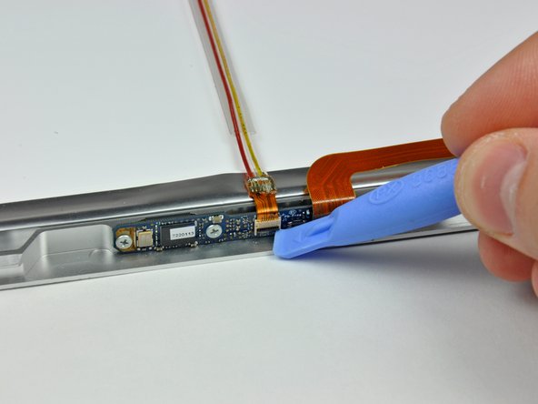
  • Insert the flat end of a spudger perpendicular to the face of the display between the plastic strip attached to the rear bezel and the front bezel.

  • Do not insert your spudger between the plastic strip and the rear bezel.

  • With the spudger still inserted, rotate it away from the display to separate the front and rear bezels.

  • Work along the right edge of the display until the rear bezel is evenly separated from the front bezel.

first image
thumb image 1
thumb image 2

Add Note Edit Step 21  ¶ 

  • Insert your spudger between the front and rear display bezels at the lower right corner of the display.

  • Pry the rear bezel away from the front bezel to slightly separate the bottom edge of the rear display bezel.

first image
thumb image 1
thumb image 2

Add Note Edit Step 22  ¶ 

  • Insert the flat end of a spudger into the gap between the rear display bezel and the clutch cover.

  • Twist the spudger to separate the lower edge of the rear display bezel from the clutch cover.

  • Work along the lower edge of the rear bezel until it is evenly separated from the clutch cover.
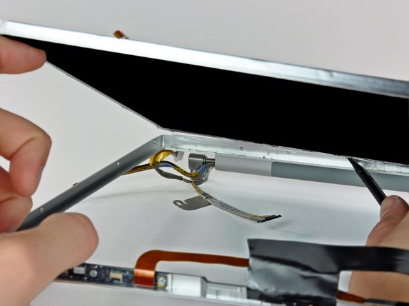
first image
thumb image 1
thumb image 2
thumb image 3

Add Note Edit Step 23  ¶ 

  • Now that the right and bottom edges of the rear bezel are slightly separated from the front bezel, use a spudger to pop the rear bezel off the tabs near the lower right corner of the display.

first image
thumb image 1
thumb image 2

Add Note Edit Step 24  ¶ 

  • Insert the flat end of a spudger between the front bezel and the plastic strip attached to the rear bezel near the screw holes at the bottom corners of the display.

  • Rotate your spudger toward the rear bezel to separate it from the front bezel.

  • If necessary, continue separating the left edge of the rear bezel off the tabs on the front display bezel.

first image

Add Note Edit Step 25  ¶ 

first image

Add Note Edit Step 26 — LCD Panel  ¶ 

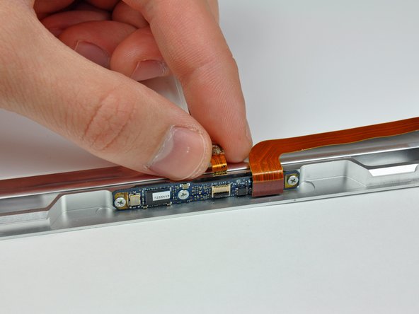
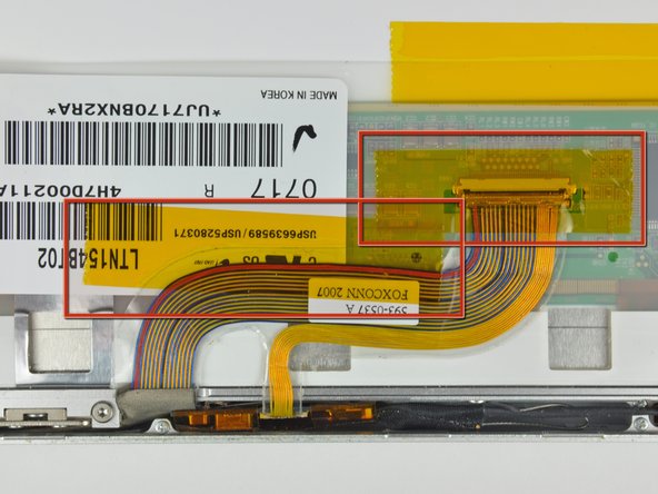
  • Peel the large piece of black tape off the LCD near the latches at the top edge of the display.

  • It is not necessary to completely remove this piece of tape.

first image

Add Note Edit Step 27  ¶ 

  • Remove the two pieces of tape covering the iSight and camera ribbon cables near the top of the display.

  • Hold the iSight cable down as you remove the tape.

first image
thumb image 1
thumb image 2
thumb image 3

Add Note Edit Step 28  ¶ 

  • Be careful not to damage the ZIF cable retainer as you use the edge of a plastic opening tool to flip it up.

  • Pull the iSight cable out of its socket on the camera board.

first image
thumb image 1
thumb image 2

Add Note Edit Step 29  ¶ 

  • First remove the strip of tape covering the iSight cable.

  • Next, peel the three orange antenna straps off the lower edge of the LCD.

  • Remove the two pieces of tape securing the display data cable to the LCD.

first image

Add Note Edit Step 30  ¶ 

  • Disconnect the display data cable by pulling its connector toward the bottom edge of the display, away from the socket on the LCD.

first image
thumb image 1
thumb image 2

Add Note Edit Step 31  ¶ 

  • Remove the four 3 mm Phillips screws from each side of the display (eight screws total).

first image

Add Note Edit Step 32  ¶ 

  • The next few steps will require you to separate the LCD from the adhesive applied to the upper and lower edges of the front bezel.

  • The adhesive is applied such that it sticks to a thin steel strip around the perimeter of the LCD. When prying your LCD away from the front panel, be sure you are separating the front panel from the steel strip on the LCD.

    • Do not simply pry on the edge of the frame as it is made of aluminum and can very easily bend!

  • Use the flat end of a spudger to gently lift one of the top corners of the LCD out of the front bezel.

first image

Add Note Edit Step 33  ¶ 

  • Work your way along the top edge of the LCD, slowly prying the attached steel strip away from the front bezel.

first image
thumb image 1
thumb image 2

Add Note Edit Step 34  ¶ 

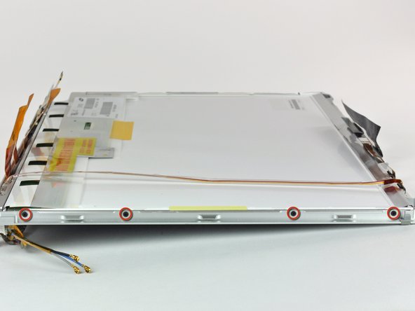
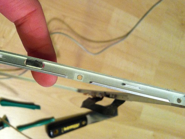
  • Now that the top edge is free, slightly lift the LCD out of the front bezel for enough room to pry the steel strip along the lower edge of the LCD away from the front bezel.

  • Pry along the lower edge of the LCD until it is freed from the adhesive on the front bezel.

first image

Add Note Edit Step 35  ¶ 

  • Lift the LCD out of the front bezel, minding any cables that may get caught.

  • Replacement Note: there are clear plastic shims attached via adhesive to the sides and bottom of the lcd panel. Be sure to transfer these shims to the replacement panel for optimum fit.

  • Don't forget to transfer the small magnet attached to the right side of the LCD to your new LCD. The absence of this magnet will prevent your MacBook Pro from entering sleep mode.

To reassemble your device, follow these instructions in reverse order.

For more information, check out the MacBook Pro 15" Core 2 Duo Models A1226 and A1260 device page.

Did you successfully follow this guide?

This guide has been completed 83 times.

Comments Add Note Comments are offturn on