Installing MacBook Core Duo LCD Panel

Replace a broken LCD panel rather than the entire display assembly.

  • Author: iRobot
  • Difficulty: Difficult
  • Add Note x
  • x 94

Save money by replacing the LCD screen without the inverter, cables, or bezels.

Sections
first image

Add Note Edit Step 1 — Battery  ¶ 

  • Use a coin to rotate the battery-locking screw 90 degrees clockwise.

first image

Add Note Edit Step 2  ¶ 

  • Lift the battery out of the computer.

first image

Add Note Edit Step 3 — Memory Cover  ¶ 

  • Remove the three evenly-spaced Phillips screws from along the rear wall of the battery compartment.

  • The screws are captive to the metal memory cover.

first image

Add Note Edit Step 4  ¶ 

  • Lift up on L-shaped memory cover, slide it to the right, and lift it out of the computer.

first image

Add Note Edit Step 5 — Upper Case  ¶ 

  • Remove the following 3 screws:

    • One 11 mm Phillips #00 in the middle of the case.

    • Two 14.5 mm Phillips #00.

  • If the screws stick in the case, you can use a magnetized screwdriver to draw them out.

  • The shorter of the three screws goes in the middle.

first image

Add Note Edit Step 6  ¶ 

  • Remove the following 3 screws from the rear wall of the battery compartment:

    • Two 3 mm Phillips #00.

    • One 4 mm Phillips #00 on the right side.

  • When reinstalling these screws, it may be helpful to push down on the lower case to line up the screw holes.

first image

Add Note Edit Step 7  ¶ 

  • Remove the two 6 mm Phillips #00 screws from either side of the right wall of the battery compartment (not the ones closest to the battery connector).

first image

Add Note Edit Step 8  ¶ 

  • Remove the four 3 mm indicated Phillips #00 screws from the front wall of the battery compartment. When working from the left, remove the 2nd, 4th, 7th and 9th screw.

first image

Add Note Edit Step 9  ¶ 

  • Remove the following 4 screws from the back of the computer:

    • Two 7 mm Philips on the far sides.

    • Two 10.5 mm Phillips toward the center.

    • Do not over-tighten these; you can cause the case to distort.

first image

Add Note Edit Step 10  ¶ 

  • Remove the two 5.2 mm shouldered Phillips #00 screws from the optical side of the computer.

  • It is not necessary to remove the similar screws on the other side of the computer.

first image

Add Note Edit Step 11  ¶ 

  • Starting near the display and working around to the front of the computer, pry up on the upper case. It is held with clips on the right above the optical drive. These will release with some firm lifting pressure.

  • Be careful when prying up the upper case. It's very easy to slice open a fingertip and thus provide the blood sacrifice the Mac gods sometimes require of those who insist on doing their own repairs.

  • There's a trackpad and keyboard ribbon connecting the upper case to the logic board, so don't pull the upper case off entirely just yet.

  • If you have trouble getting the clips to release, be careful that you are not prying the plastic top of the upper case away from its metal frame.

first image

Add Note Edit Step 12  ¶ 

  • While holding up the upper case, use a spudger to pry up the orange trackpad and keyboard cable from its connector.

  • If you happen to break your upper case cable when removing the upper case, we stock the cable individually and we have a guide that makes replacing it easy.

first image

Add Note Edit Step 13 — Optical Drive  ¶ 

  • Grasp the white plastic tab attached to the hard drive and pull it to the left, removing the hard drive from the computer.

first image

Add Note Edit Step 14  ¶ 

  • Remove the two Phillips screws from the front edge of the optical drive.

  • The shorter screw is recessed nearest the RAM modules.

first image

Add Note Edit Step 15  ¶ 

  • Disconnect the orange optical drive ribbon cable from the logic board.

first image

Add Note Edit Step 16  ¶ 

  • Disconnect the newly-revealed display data cable. If there is no pull-tab on the top of the connector, it may be helpful to use a spudger to disconnect this connector.

first image

Add Note Edit Step 17  ¶ 

  • Disconnect the (once again) newly-revealed hard drive cable.

first image

Add Note Edit Step 18  ¶ 

  • Peel up the foil tape between the fan and the optical drive.

  • Remove the Phillips screw securing the display data cable to the metal framework.

first image

Add Note Edit Step 19  ¶ 

  • Pull up the display data cable from along the edge of the optical drive to reveal a silver Phillips screw.

first image

Add Note Edit Step 20  ¶ 

  • Remove the Phillips screw securing the optical drive.

  • The Bluetooth cable may be covering the screw; carefully push it aside before removing the screw.

  • Do not over-tighten this screw when re-mounting. You could break the plastic enclosure.

  • After removing the screw, push the metal tab backwards, towards the fan, to release the front of the optical drive.

first image

Add Note Edit Step 21  ¶ 

  • Lift the Bluetooth antenna board from the right side of the optical drive.

first image

Add Note Edit Step 22  ¶ 

  • Deroute the hard drive cable from along the front of the optical drive.

first image

Add Note Edit Step 23  ¶ 

  • Lift the front edge of the optical drive and slide it up and out of the computer.

first image

Add Note Edit Step 24 — C-Channel  ¶ 

  • Remove the following 3 screws:

    • Two 3 mm Phillips near the right speaker.

    • One 6 mm Phillips threaded through a hole in a plastic finger above the subwoofer.

  • Be careful not to over-tighten the screw above the subwoofer too tight or the plastic could crack.

first image

Add Note Edit Step 25  ¶ 

  • Lift the right speaker out of its housing and set it to the side.

first image

Add Note Edit Step 26  ¶ 

  • Using a spudger, gently pry up the white plastic slot and slide the metal c-channel to the right and away from the display.

first image

Add Note Edit Step 27 — Display  ¶ 

  • Use a spudger to carefully disconnect the microphone cable from the logic board. You'll want to work from side to side, and slowly wiggle the connector out of its socket.

  • Pulling on this connector vertically will break the socket off the logic board. This connector should be removed horizontally by gently pulling the microphone cable toward the screen while working a spudger between the connector and the socket.

first image

Add Note Edit Step 28  ¶ 

  • Lift up on the black right speaker cable with one hand, and deroute the silver microphone cable from the silver metal clip just above the right RAM slot.

first image

Add Note Edit Step 29  ¶ 

  • Deroute the silver microphone cable and gray display data cable from the tabs at the bottom of the subwoofer.

first image

Add Note Edit Step 30  ¶ 

  • Remove the single Phillips screw securing the ground loop in the display data cable located just above the Bluetooth board.

first image

Add Note Edit Step 31  ¶ 

  • Disconnect the two antenna cables from the Airport card, and the black inverter cable from the logic board. (Pull vertically on all three.)

first image

Add Note Edit Step 32  ¶ 

  • Remove the following 2 screws from the right hinge mount:

    • One 6 mm Phillips on the left side of the hinge mount.

    • One 10 mm Phillips on the right side of the hinge mount.

  • Lift the right hinge mount out of the computer.

first image

Add Note Edit Step 33  ¶ 

  • Hold the display with one hand while removing the screws from the left hinge mount.

  • Remove the following 3 screws from the left hinge mount:

    • One 6 mm smaller diameter Phillips from the right side.

    • One 6 mm larger diameter Phillips from the middle.

    • One 10 mm Phillips from the left side.

  • Lift the left hinge mount out of the computer.

first image

Add Note Edit Step 34  ¶ 

  • Grasp the display assembly on either side, and lift it up and out of the computer.

first image

Add Note Edit Step 35 — Front Display Bezel  ¶ 

  • The following steps should be identical for both white and black MacBooks.

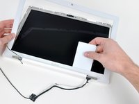
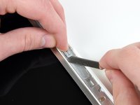
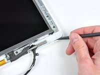
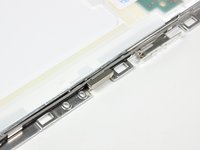
  • Use a thin plastic card to release the tabs holding the front display bezel to the display assembly. There are five tabs along the left side of the display bezel.

  • Don't use a card that cannot be replaced if damaged. The clips can be difficult to remove and the card can bend and break, rendering it useless.

first image

Add Note Edit Step 36  ¶ 

  • Continue to free the tabs along the the top edge of the display assembly.

  • Be careful when working near the iSight camera.

first image

Add Note Edit Step 37  ¶ 

  • Next, free the five tabs securing the display bezel on the right side.

first image
thumb image 1
thumb image 2

Add Note Edit Step 38  ¶ 

  • Lift up the front display bezel from the top and use your plastic card to free the tabs along the bottom edge of the display bezel.

  • Make sure that your card is between the metal frame around the LCD panel and the display bezel and not touching the LCD panel itself.

  • After freeing all holding tabs, lift the front display bezel away from the display assembly.

first image
thumb image 1
thumb image 2

Add Note Edit Step 39  ¶ 

  • Sometimes when removing the front display bezel, the retaining clips that should remain captive in the LCD brackets come out with the front display bezel. Follow this and the next step to transfer the clips back to the LCD bracket.

  • Use a metal spudger or another thin tool to carefully pry the gray plastic clips off the tabs molded into the front display bezel.

  • Be careful, as the clips are made of thin plastic and are inherently delicate.

first image
thumb image 1
thumb image 2

Add Note Edit Step 40  ¶ 

  • Insert the longer end of the retaining clip beneath the edge of its recess cut into the LCD bracket.

  • Use the edge of a metal spudger to push the shorter tab on the other side of the retaining clip into the recess cut into the LCD bracket.

  • The second picture shows the LCD bracket properly installed.

first image

Add Note Edit Step 41 — Clutch Cover  ¶ 

  • Remove the three 4.2 mm Phillips screws securing the clutch cover.

first image

Add Note Edit Step 42  ¶ 

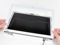
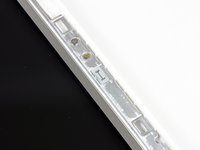
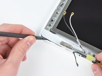
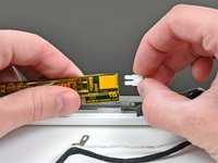
  • While holding the display down with one hand, use your other hand to lift the clutch cover off the clutch hinges.

  • It may help to wiggle the clutch cover as you pull it up from the display.

first image

Add Note Edit Step 43  ¶ 

  • Lift up the right side of the clutch cover and guide the display data and iSight cables through the gap in the clutch cover.

  • Lift the clutch cover out of the display assembly.

  • During reassembly, make sure not to pinch the pink and white inverter cable when snapping the clutch cover back into place.

first image
thumb image 1
thumb image 2

Add Note Edit Step 44 — LCD Assembly  ¶ 

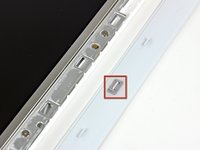
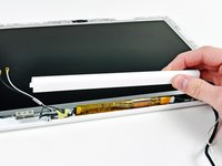
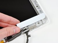
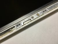
  • Remove the small piece of foam tape stuck down above each of the bezel covers.

first image
thumb image 1
thumb image 2

Add Note Edit Step 45  ¶ 

  • Use a spudger to slide the left bezel cover towards the LCD panel.

    • Do not lift up vertically on the cover! Unlike the large display bezel, this one has horizontal hooks to keep it in place. These will break easily.

  • Lift the left bezel cover off the display assembly.

first image
thumb image 1
thumb image 2

Add Note Edit Step 46  ¶ 

  • Use a spudger to slide the right bezel cover toward the LCD panel.

  • Lift the right bezel cover off the display assembly.

first image
thumb image 1
thumb image 2

Add Note Edit Step 47  ¶ 

  • Lift the inverter out of the display slightly and disconnect the backlight cable from its right side.

  • Place the inverter back down in its recess.

first image

Add Note Edit Step 48  ¶ 

  • Remove the single 3.2 mm Phillips screw securing the display data cable to the right clutch hinge.

first image

Add Note Edit Step 49  ¶ 

  • Move the display data cable out from under the mounting arm of the right clutch hinge.

first image

Add Note Edit Step 50  ¶ 

  • Remove the twelve 4.2 mm Phillips screws securing the LCD assembly to the rear display bezel.

  • Make sure you pay attention to how the microphone cable (and antenna cable on some models) are routed around the outside of the two screws nearest to the bottom of the screen (on both left and right). It's easy to damage the cables if not routed properly when putting these screws back on.

first image

Add Note Edit Step 51  ¶ 

  • Lift the LCD assembly out of the rear display bezel, minding any cables that may get caught.

first image

Add Note Edit Step 52  ¶ 

  • Be sure to keep track of the small magnet along the left side of the display. It may be stuck to the LCD frames or to the rear display bezel. When installing it, be sure short side is facing upward.

first image

Add Note Edit Step 53 — LCD Panel  ¶ 

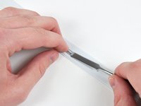
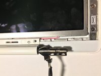
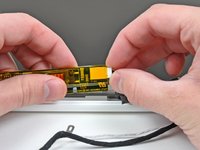
  • Turn the LCD panel assembly over so that the screen is face down. You may want to use a cloth on your worksurface to prevent scratching the screen.

  • Peel up all the yellow tape securing the display data and iSight cables to the back of the LCD panel.

  • You'll need to transfer the tape over to your new display when reassembling the computer.

first image

Add Note Edit Step 54  ¶ 

  • Disconnect the display data cable from the back of the display.

first image

Add Note Edit Step 55  ¶ 

  • Disconnect the iSight cable from the top of the display.

first image

Add Note Edit Step 56  ¶ 

  • Lift up the display data and iSight cables and move them to the side. It is not necessary to entirely remove these cables from the display assembly.

  • De-route the microphone cable from the right side of the LCD assembly.

  • On Core 2 Duo models, also de-route the antenna cable from the left side of the LCD assembly.

first image

Add Note Edit Step 57  ¶ 

  • Remove the three 3.1 mm Phillips screws along the left edge of the display.

first image

Add Note Edit Step 58  ¶ 

  • Remove the two 3.1 mm Phillips screws securing the iSight holder to the top of the display.

  • Make sure to remove the screws securing the metal bracket to the edge of the display and not the screws in the iSight board itself.

first image

Add Note Edit Step 59  ¶ 

  • Remove the three 3.1 mm Phillips screws along the right edge of the display.

first image

Add Note Edit Step 60  ¶ 

  • Lift up the LCD panel by its bottom edge and slide it out of the metal mounting brackets.

To reassemble your device, follow these instructions in reverse order.

For more information, check out the MacBook Core Duo device page.

Did you successfully follow this guide?

This guide has been completed 94 times.

Comments Add Note Comments are offturn on