Introduction
Replacing the battery requires a fine tip soldering iron and is a difficult job that only experienced solderers should attempt.
What you need
-
-
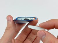
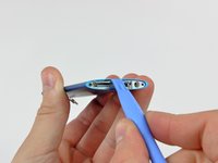
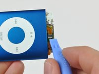
Insert the edge of an iPod opening tool into the gap between the outer case and the top bezel.
-
Pry the top bezel off the adhesive securing it to the display retainer.
-
-
-
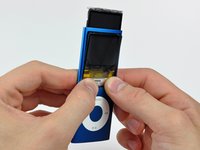
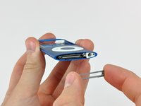
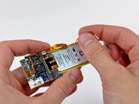
Use the edge of an iPod opening tool to separate the hold switch from the adhesive securing it to the top edge of the display.
-
-
-
-
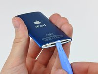
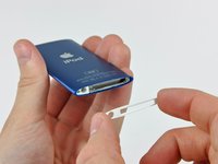
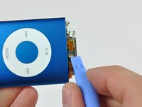
Insert an iPod opening tool between the bottom bezel and the dock connector.
-
Separate the bottom bezel from the adhesive securing it to the Nano and set it aside.
-
-
-
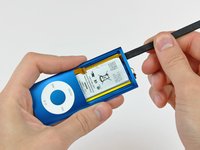
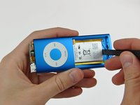
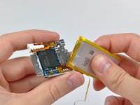
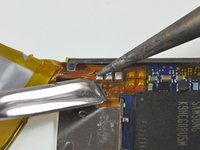
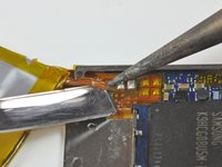
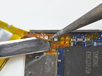
Peel the hold switch cable from along the edge of the battery and lay it aside. The hold switch cable is not attached to the battery.
-
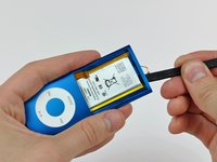
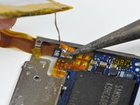
Pry the battery off the adhesive securing it to the metal tray on the logic board.
-


To reassemble your device, follow these instructions in reverse order, while being careful not to damage the iPod.
Cancel: I did not complete this guide.
183 other people completed this guide.

40 Guide Comments
There is one small point which is worth a mention here.After disconnnecting the screen by flicking up a little black bit on the ZIF Connector, I went on to open the next ZiF (The Click Switch)
Yes- bits of ZIF connector everywhere.I actually had to examine a new Click Switch circuit carefully to find that this one is different.
Yes - you flick the White bit. Do apple do this just to keep us on our toes?
I have taken the nano apart and started to use a solder iron to remove the old battery. I must have pulled on the battery before fully melting the solder and have pulled off two of the three tabs from the board.
Can this be fixed?
I think you might have to get a new board or figure out how to fix the pads with wire. I believe there are tutorials on that.
Ad123re -
I tried what Bradley suggested because it really seems easier than to solder the new battery to the iPod circuit board, which is really tiny. Still I couldn't do it. The battery pads are very fragile and I had an hard time folding the leads and the battery circuit board so that it looked the way it originally was. This was the part where I failed because afterwards I wasn't able to insert the battery plus the iPod circuit board inside its case again and ended it breaking it.
When I soldered my battery in I first touched the top and bottom of the pads on the new battery with flux and then added a little solder to the top and bottom of the pads. When I put the pads in place I only had to apply a quick touch and it soldered on perfectly.
Overall it was a real pain! :)