Installing iPad 3G Battery Replacement

Replace a worn out battery on your iPad 3G.

  • Add Note x
  • x 9

Use this guide to replace your iPad's battery.

first image
thumb image 1
thumb image 2

Add Note Edit Step 1 — Display Assembly  ¶ 

  • The iPad shown in the photos may look slightly different from your iPad, but the procedure is the same.

  • Insert a metal spudger between the right edge of the display assembly and the rear panel assembly.

  • Rotate the spudger away from you to release the tabs along the top edge of the display.

first image
thumb image 1
thumb image 2

Add Note Edit Step 2  ¶ 

  • Insert a second metal spudger between the top edge of the display assembly and the rear panel assembly to keep the tabs from snapping back into place.

  • Pry the display assembly away from the rear panel.

first image
thumb image 1
thumb image 2

Add Note Edit Step 3  ¶ 

  • Continue prying the display assembly away from the rear panel along the bottom and left edges of the iPad.

  • Use extreme caution as you approach the top edge of the iPad. The digitizer ribbon cable is located near the edge of the rear panel and can easily be damaged.

first image

Add Note Edit Step 4  ¶ 

  • Lift the display assembly away from the rear panel assembly by its bottom edge.

  • Do not excessively lift the display assembly off the rest of the iPad, as a fragile antenna cable with very little slack still connects the two components.

first image

Add Note Edit Step 5  ¶ 

  • Use the flat end of a spudger to pry the antenna connector closest to the bottom of the iPad up off its socket on the communications board.

first image

Add Note Edit Step 6  ¶ 

  • In the following steps, you will disconnect the three cables attaching the display assembly to the logic board. The cables are for the following components:

    • Digitizer

    • Ambient Light Sensor

    • Display Data Cable

first image
thumb image 1
thumb image 2
thumb image 3

Add Note Edit Step 7  ¶ 

  • Use the edge of an iPod opening tool to flip up the retaining flaps holding the digitizer ribbon cables in their sockets on the logic board.

  • Be sure you are flipping up the retaining flap, not the socket itself.

  • Pull the digitizer ribbon cables straight out of their sockets.

first image

Add Note Edit Step 8  ¶ 

  • Use an iPod opening tool to remove the ambient light sensor connector from its socket by gently prying upward.

first image
thumb image 1
thumb image 2

Add Note Edit Step 9  ¶ 

  • Disconnect the display data cable from the main board by flipping up the metal retainer by its black plastic pull tab.

  • Pull the cable connector away from its socket.

  • Pull the connector parallel to the face of the logic board.

first image

Add Note Edit Step 10  ¶ 

  • Remove the display assembly from the rear panel assembly.

first image

Add Note Edit Step 11 — Communications Board  ¶ 

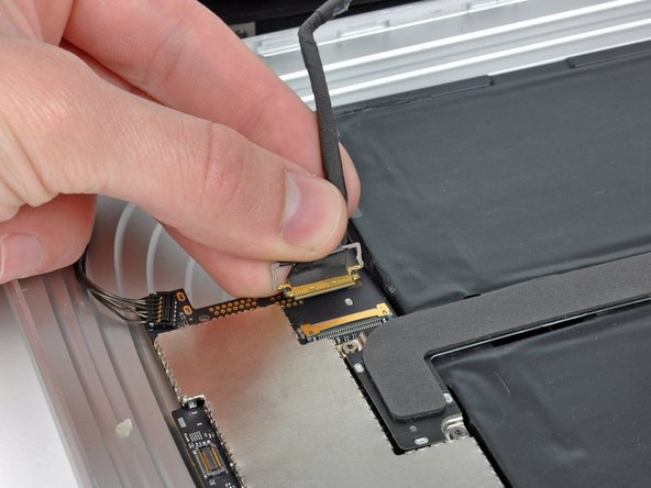
  • Use the edge of an iPod opening tool to carefully pry the remaining antenna connector up off the communications board.

first image
thumb image 1
thumb image 2

Add Note Edit Step 12  ¶ 

  • De-route the control button cable along the top edge of the communications board.

  • Pull the communications cable upward to lift its connector up and out of the socket on the logic board.

first image

Add Note Edit Step 13  ¶ 

  • Remove the single T5 Torx screw securing the communications board to the rear case.

first image
thumb image 1
thumb image 2

Add Note Edit Step 14  ¶ 

  • If necessary, lift the right edge of the communications board upward to release it from the adhesive pad attached to the rear case.

  • Pull the communications board away from its socket on the logic board.

first image

Add Note Edit Step 15 — Logic Board  ¶ 

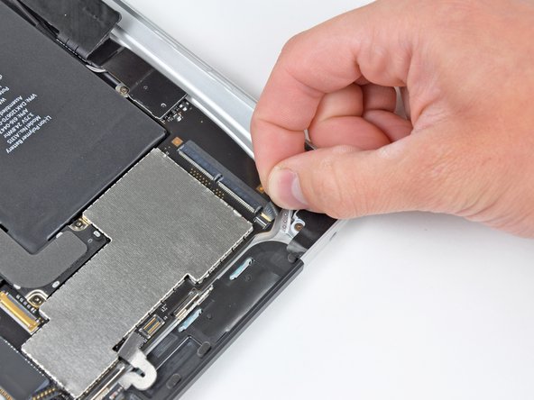
  • Carefully peel back the rubber EMI shield covering the GPS antenna socket.

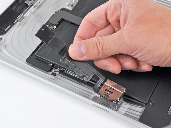
  • Use the edge of an iPod opening tool to flip up the GPS ribbon cable retaining flap attached to the GPS cable's socket on the logic board.

  • Be sure you pry up on the retaining flap, not the socket itself.

first image

Add Note Edit Step 16  ¶ 

  • Pull the GPS antenna ribbon cable out of its socket.

first image
thumb image 1
thumb image 2

Add Note Edit Step 17  ¶ 

  • Use the edge of an iPod opening tool to pry up the retaining flap on the headphone jack/microphone socket.

  • Be sure you pry up on the retaining flap, not the socket itself.

  • Pull the headphone jack/microphone ribbon cable out of its socket.

  • Pull the cable toward the left side of the iPad.

first image

Add Note Edit Step 18  ¶ 

  • Use an iPod opening tool to pry the SIM board connector up off its socket on the logic board.

first image

Add Note Edit Step 19  ¶ 

  • Fold the SIM cable toward the bottom of the iPad to access the speaker connector.

  • Use the edge of an iPod opening tool to pry the speaker connector up and out of its socket on the logic board.

  • Pry up from beneath the wires.

first image

Add Note Edit Step 20  ¶ 

  • Remove the following screws securing the logic board to the rear panel assembly.

    • Two 4.56 mm T5 Torx screws.

    • Two 3.76 mm T5 Torx screws.

first image

Add Note Edit Step 21  ¶ 

  • Use the edge of an iPod opening tool to carefully pry the dock cable connector straight up off the logic board.

first image

Add Note Edit Step 22  ¶ 

  • Lift the logic board out of the rear panel assembly.

first image
thumb image 1
thumb image 2

Add Note Edit Step 23 — Battery Replacement  ¶ 

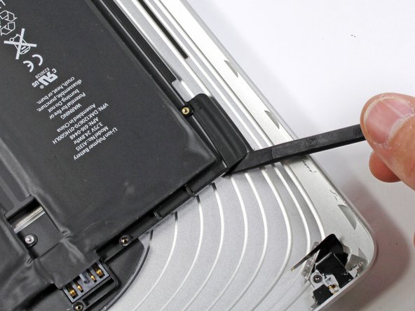
  • Use the edge of an iPod opening tool to release the SIM board from the adhesive securing it to the rear case.

  • Remove the SIM board from your iPad.

first image

Add Note Edit Step 24  ¶ 

  • Remove the two 2.84 mm T5 Torx screws securing the speaker assembly to the rear panel assembly.

  • Remove the single T5 Torx screw securing the middle of the dock cable to the rear panel assembly.

first image

Add Note Edit Step 25  ¶ 

  • Remove the two 2.84 mm T5 Torx screws securing the dock connector cable to the rear case.

first image

Add Note Edit Step 26  ¶ 

  • Using an iPod opening tool, carefully remove the plastic cover shielding the WiFi/Bluetooth board and dock connector cable.

first image

Add Note Edit Step 27  ¶ 

  • Carefully pry the Wi-Fi and Bluetooth antennas up from their respective sockets on the Wi-Fi/Bluetooth board.

first image

Add Note Edit Step 28  ¶ 

  • Lift the dock connector cable out of the rear panel assembly.

first image
thumb image 1
thumb image 2

Add Note Edit Step 29  ¶ 

  • De-route the speaker cable from the left side of the battery case.

  • De-route the Wi-Fi antenna through its channel in the speaker assembly.

first image
thumb image 1
thumb image 2

Add Note Edit Step 30  ¶ 

  • Lift the speaker assembly and push it forward until the ports clear the bottom side of the lower case.

  • Remove the speaker assembly from the rear panel assembly.

first image
thumb image 1
thumb image 2

Add Note Edit Step 31  ¶ 

  • The battery is held to the rear panel by an excessive amount of adhesive. Proceed with patience and caution.

  • Use the flat end of a spudger to gently pry the battery up from the the lower case.

  • Gently continue to enlarge the gap by wiggling the spudger and running it along the right side of the battery.

  • Continue to pry until the right side of the battery is free from the rear panel.

first image
thumb image 1
thumb image 2

Add Note Edit Step 32  ¶ 

  • Insert the flat end of a spudger under the top edge of the battery and continue to separate the adhesive.

  • Continue doing so until the top of the battery is free from the rear panel.

first image
thumb image 1
thumb image 2

Add Note Edit Step 33  ¶ 

  • When there is enough clearance, use your hands to peel the battery off any adhesive still securing it to the rear panel.

  • Remove the battery from the rear panel.

To reassemble your device, follow these instructions in reverse order.

For more information, check out the iPad 3G device page.

Did you successfully follow this guide?

This guide has been completed 9 times.

Comments Add Note Comments are offturn on