Introduction
Use this guide to replace your MacBook Pro's display assembly.
What you need
-
-
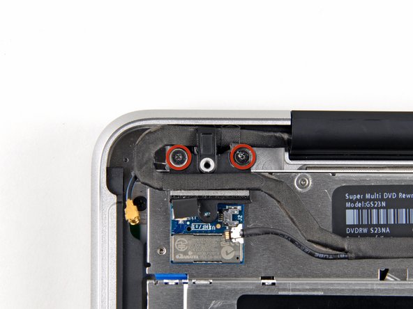
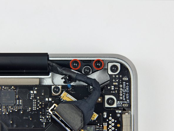
Remove the following ten screws securing the lower case to the upper case:
-
Seven 3 mm Phillips screws.
-
Three 13.5 mm Phillips screws.
-
-
-
Three Pentalobe screws secure the battery to the upper case. They can be removed with this special driver.
-
-
-
-
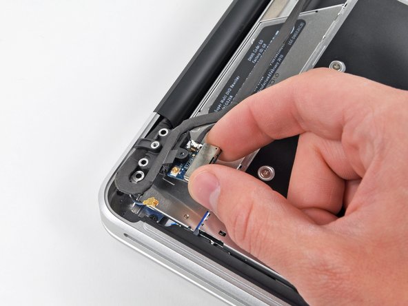
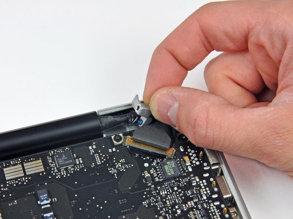
Hold the end of the cable retainer down with one finger while you use the tip of a spudger to slightly lift the other end and rotate it away from the camera cable connector.
-
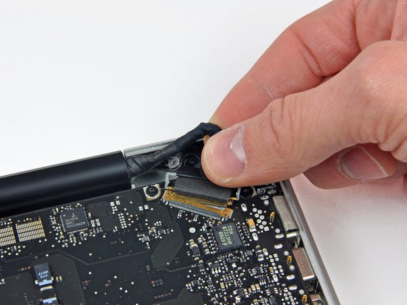
Pull the camera cable away from its socket on the logic board.
-
-
-
Grab the upper case with your right hand and rotate it slightly toward the top of the display so the upper display bracket clears the edge of the upper case.
-
Rotate the display slightly away from the upper case.
-
Lift the display up and away from the upper case, minding any brackets or cables that may get caught.
-


To reassemble your device, follow these instructions in reverse order.
To reassemble your device, follow these instructions in reverse order.
Cancel: I did not complete this guide.
27 other people completed this guide.

3 Comments
Will a 2010 A1286 Display assembly fit a 2009 A1286 Macbook Pro?
I greatly appreciated your comment in Step 8 saying: “Apple sticks a small strip of clear plastic with adhesive applied to one side to the logic board behind the camera cable connector to keep it in its socket“.
My problem was that I had an old Macbook Pro whose camera cable was out of its socket and I could not get it in because this piece of plastic was in the way. I had no idea what it was. It was not clear to me if it was an IC or some other important component. Your comment clarified what it was and its purpose.
Pushing down on it at one end did not achieve anything, so I have just lifted it up and off the board using a small scalpel blade.
I will use some tape to hold the cable connector in its socket.
Thank you