Introduction
The main board of the machine.
What you need
-
-
Power down your Mac mini, disconnect all of the cables, and flip it over.
-
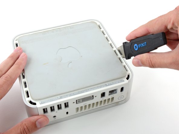
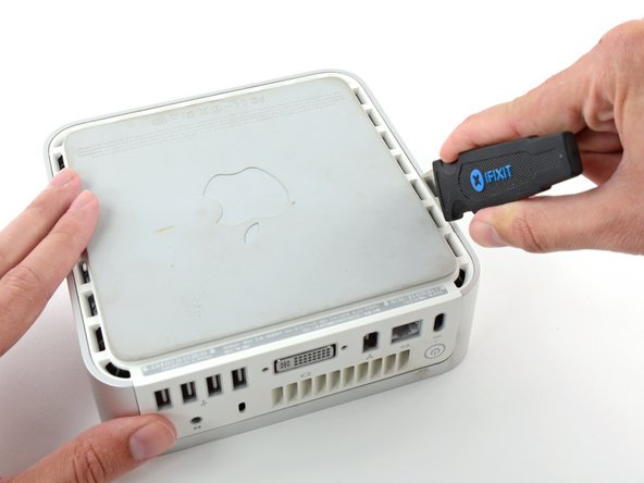
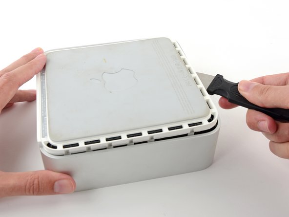
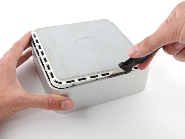
Insert the Jimmy into the crack between the aluminum top housing and the plastic lower housing.
-
The Jimmy should reach a stop about 3/8" down.
-
-
-
Grasp the Airport antenna board and lift it off of the two plastic posts holding it in place. You may need to push back the black plastic tab jutting through the lower left corner of the board.
-
-
-
-
With your free hand, pull the Bluetooth cable up from Bluetooth board and unplug the Airport antenna cable from the right of the Airport card. Caution: both of these connections are very small. When re-assembling unit after repair, you may want to remove the two screws holding the airport card to the assembly and lift the card up and out to re-attach the cables.
-
-
-
Remove the two silver Phillips screws from the corners of the wireless interface board.
-


To reassemble your device, follow these instructions in reverse order.
To reassemble your device, follow these instructions in reverse order.
Cancel: I did not complete this guide.
12 other people completed this guide.
Attached Documents

3 Comments
You are supposed to replace the heat transfer pad on the bottom case when you remove the logic board. If this pad doesn’t make good contact with the GPU, you’ll get overheating and the unit will goto sleep after a short time.
My Mac Mini G4 is missing the screws for the HDD/DVD carrier and the one screw for the logic board. Can you tell me where I can buy these or give me specs so I can find replacements on eBay?