Introduction
Upgrade your mini's aging Core Duo processor to a blazing Core 2 Duo.
What you need
-
-
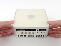
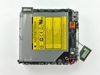
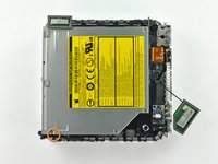
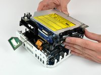
Power down your Mac mini, disconnect all of the cables, and flip it over.
-
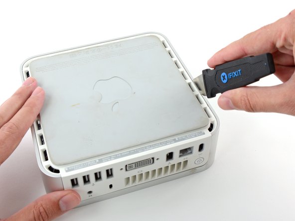
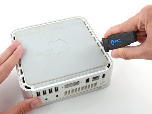
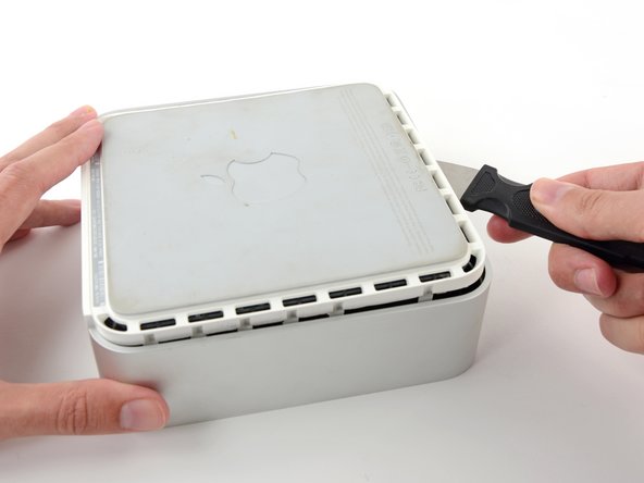
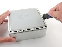
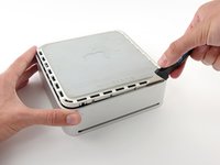
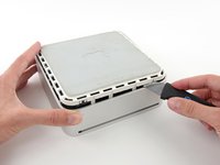
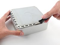
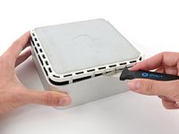
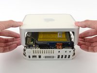
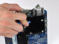
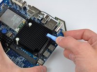
Insert the Jimmy into the crack between the aluminum top housing and the plastic lower housing.
-
The Jimmy should reach a stop about 3/8" down.
-
-
-
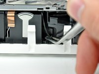
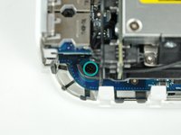
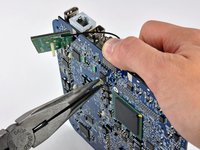
Slightly squeeze the two retaining arms toward each other and lift the AirPort antenna off its post.
-
-
-
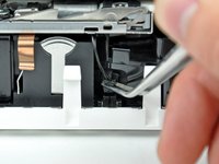
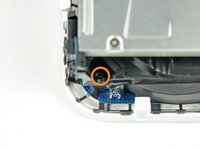
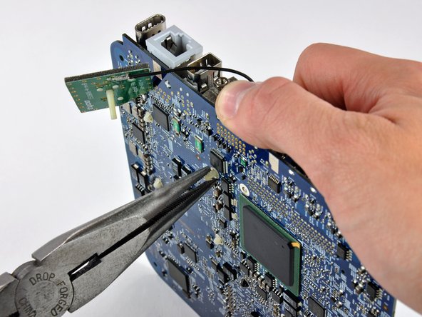
Tool used on this step:Tweezers$4.99
-
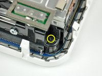
Firmly grasp the power button cable connector with a pair of tweezers and lift it straight up off the logic board.
-
-
-
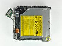
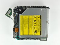
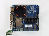
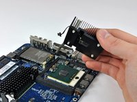
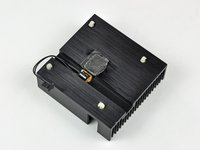
A spring loaded plastic pin at each corner of the heat sink holds it firmly against the face of the processor.
-
-
-
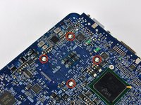
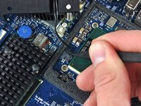
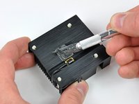
Using a plastic opening tool (or similar) in one hand, push down one pin holding the heat sink on the logic board. The spring under the pin will provide moderate resistance.
-
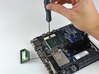
While holding the pin down from the heat sink side of the board, use a pair of pliers in your other hand on the underside of the board to squeeze both barbs against the plastic shaft of the pin.
-
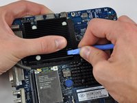
With both barbs squeezed together, push the pin through its hole in the logic board.
-
Repeat this process for each of the four pins holding the heat sink on the logic board.
-
-
-
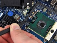
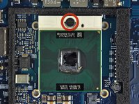
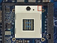
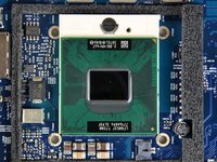
To aid in installation, processors and sockets have a small alignment arrow (shown in red) so the chip is installed in the correct orientation.
-
Align the chip so that the arrow in its upper right corner corresponds to the arrow molded into the upper right corner of the socket.
-
Carefully lower the processor onto its socket.
-
Note that if you are upgrading from a core solo or core duo processor to a core 2 duo processor and wish to run operating systems of Lion or later, you must delete the hidden file /System/Library/CoreServices/PlatformSupport.plist after the upgrade.
-
-
-
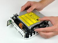
Now that the processor is in place, turn your attention to the heat sink.
-
Apple uses a thermally conductive film that must be removed prior to reinstalling the heat sink.
-
Use a razor blade (or anyother flat object such as a credit card, etc.) to remove all of the old solidified thermal material from the heat sink.
-
Next use a small amount of rubbing alcohol to remove all traces of the old thermal material.
-
Allow the heat sink to dry before proceeding.
-
-
-
Apply a thin layer of thermal paste to the reflective silicon face of the processor.
-
Check out our thermal paste guide for detailed instructions on applying thermal paste.
-


To reassemble your device, follow these instructions in reverse order.
Cancel: I did not complete this guide.
171 other people completed this guide.

44 Guide Comments
I'm learning from cpu-world.com that the Core Duo (and Core Solo) are 32-bit architecture, whereas the Core 2 Duo is a 64-bit design. Does this matter in any way?
Hi Richard. I realize this post is very old, but did you ever get an answer to your question as to whether the 64-bits of the Core 2 Duo Processor will be recognized/utilized in the 32-bit architecture of the Mac Mini A1176? Thanks, John
Hi. I'm afraid I can no longer answer the question "does it matter in any way", since I eventually upgraded to a new Mac Mini.
I can say that it didn't *seem* to matter, which means no software failed to run or performed noticeably poorly because of the upgrade. But I'm not especially performance sensitive, so it is possible that all/most/some software was running in 32-bit mode and not taking advantage of the higher throughput of a 64-bit architecture. The most CPU intense stuff I was running when I decided to upgrade was: Parallels running WinXP and some Windows-only legal software, along with Chrome with far too many tabs open, and iTunes. That proved to be too much, and it'd slow to a crawl too often. But I think the upgrade kept me on that iMac and extra two or three years, and was an interesting exercise.
Richard -
Hi, the processor will work just fine, but it’s recommended to do an EFI upgrade from 1,1 to 2,1, then you can run Lion and unofficially newer OSes
When going to all the trouble of replacing the CPU, a few other upgrades can be done at the same time:
- Upgrade RAM to 2GB maximum (required for OS X Lion), for example, Crucial CT541128
- Upgrade internal 2.5" SATA hard drive to larger size, and/or faster 7400 RPM or SDD.
- Replace PRAM battery with a fresh one (CR2032 lithium 3V)