
Motherboard Disconnection (Screen)

Prerequisite Only
This guide is only intended to be used as a prerequisite for other guides. It's incomplete by itself.

What you need

  1. Motherboard Disconnection (Screen), Insert an opening pick: step 1, image 1 of 2 Motherboard Disconnection (Screen), Insert an opening pick: step 1, image 2 of 2
    • Lay your eReader down so the back cover is facing up.

    • Insert the flat edge of an opening pick between the frame and the bottom left corner of the back cover.

    • Push the pick downwards at a slight angle until it slides under the back cover.

  2. Motherboard Disconnection (Screen), Release the bottom clips: step 2, image 1 of 3 Motherboard Disconnection (Screen), Release the bottom clips: step 2, image 2 of 3 Motherboard Disconnection (Screen), Release the bottom clips: step 2, image 3 of 3
    • Slide the pick toward the bottom right corner to release the clips along the bottom edge.

  3. Motherboard Disconnection (Screen): step 3, image 1 of 2 Motherboard Disconnection (Screen): step 3, image 2 of 2
    • Remove the pick and reinsert it under the bottom left corner.

    • Angle the pick flat under the back cover and rotate it around the bottom left corner to release its clips.

    • If you're having trouble, try twisting the pick to lift the corner clips out of their slots.

  4. Motherboard Disconnection (Screen), Release the left clips: step 4, image 1 of 3 Motherboard Disconnection (Screen), Release the left clips: step 4, image 2 of 3 Motherboard Disconnection (Screen), Release the left clips: step 4, image 3 of 3
    • Slide the pick toward the top left corner to release the clips along the left edge.

  5. Motherboard Disconnection (Screen), Remove the back cover: step 5, image 1 of 3 Motherboard Disconnection (Screen), Remove the back cover: step 5, image 2 of 3 Motherboard Disconnection (Screen), Remove the back cover: step 5, image 3 of 3
    • At this point, you should be able to grip the back cover and release its remaining clips. If not, slide a pick under the perimeter of the back cover until you can grip an edge.

    • Grip the left edge of the back cover and lift it away from the eReader to release the remaining clips.

    • Remove the back cover.

    • During reassembly, align the back cover over the eReader and press along the perimeter until all its clips snap back into place.

  6. Motherboard Disconnection (Screen), Coating information: step 6, image 1 of 3 Motherboard Disconnection (Screen), Coating information: step 6, image 2 of 3 Motherboard Disconnection (Screen), Coating information: step 6, image 3 of 3
    • The entire surface of the eReader's internals is covered in a thin, plastic-like waterproof coating. Keep the following in mind as you continue disassembly:

    • While this won't hurt your device, removing the coating compromises the device to potential water damage.

    • The coating is brittle and can flake into many small pieces. Heating the coating helps, but working with it is still a time-consuming process.

    • The ZIF connector locking tabs are coated in a gel that can jam the hinge and keep the locking tab from completely unlocking. Make sure the tabs are completely upright before disconnecting any cables.

    • Depending on your repair, you might have to remove the coating from ZIF connectors and their cables.

  7. Motherboard Disconnection (Screen), Soften the battery connector coating: step 7, image 1 of 2 Motherboard Disconnection (Screen), Soften the battery connector coating: step 7, image 2 of 2
  8. Motherboard Disconnection (Screen), Remove the battery connector coating: step 8, image 1 of 3 Motherboard Disconnection (Screen), Remove the battery connector coating: step 8, image 2 of 3 Motherboard Disconnection (Screen), Remove the battery connector coating: step 8, image 3 of 3
    • Use the tip of a spudger to scrape up the coating along the white battery connector head—enough so you can grab clumps of it with pointed tweezers.

  9. Motherboard Disconnection (Screen): step 9, image 1 of 3 Motherboard Disconnection (Screen): step 9, image 2 of 3 Motherboard Disconnection (Screen): step 9, image 3 of 3
    • Use pointed tweezers to peel off all of the coating around the battery connector head and its socket.

    • If the coating becomes too brittle and hard to peel off, reheat the connector and try again.

    • This is a meticulous process! Failure to remove enough of the coating could damage the plastic head during disconnection, so take your time!

  10. Motherboard Disconnection (Screen), Disconnect the battery: step 10, image 1 of 2 Motherboard Disconnection (Screen), Disconnect the battery: step 10, image 2 of 2
    • Insert the point of a spudger under the edge of the battery connector head opposite of the cable.

    • There's a surface-mounted component close to the connector. Be careful not to touch it with your spudger!

    • Lift up the connector with the spudger to separate the rest of the coating and disconnect the battery.

    • During reassembly:

    • Inspect the connector head and its socket for any remaining coating that could prevent a good connection.

    • Peel off the coating, heating the area when the coating becomes too brittle.

    • It doesn't have to look pretty! You just need to remove enough coating so the connector head sits properly in its socket.

  11. Motherboard Disconnection (Screen), Battery information: step 11, image 1 of 1
    • When working on or near the battery, don't use sharp metal tools to avoid puncturing and shorting the battery! A punctured battery can leak dangerous chemicals and catch fire.

    • If your battery comes with stretch release adhesive, follow the next two steps to remove them.

    • Otherwise, skip ahead three steps to remove the normal adhesive.

  12. Motherboard Disconnection (Screen), Remove the stretch release adhesive: step 12, image 1 of 3 Motherboard Disconnection (Screen), Remove the stretch release adhesive: step 12, image 2 of 3 Motherboard Disconnection (Screen), Remove the stretch release adhesive: step 12, image 3 of 3
    • Use tweezers to pull on the battery adhesive strip's pull tab until you can grip it with your fingers.

    • While holding the battery in place, pull the strip out slowly and steadily at a low angle. Give it plenty of time to stretch and un-stick from under the battery.

    • You can also wrap the adhesive strip around a spudger and "roll" it for a more consistent pull.

    • If the adhesive strip breaks off, try to retrieve it using your fingers and continue pulling—but don’t pry under the battery.

    • If you can't retrieve a strip, don't worry! Remove as much adhesive as possible and skip down two steps for an alternate method.

  13. Motherboard Disconnection (Screen), Remove the battery: step 13, image 1 of 2 Motherboard Disconnection (Screen), Remove the battery: step 13, image 2 of 2
    • Lift the battery out of the frame and remove it.

    • If you're transferring the battery to a new screen, inspect the battery for any dents or deformations.

    • Never reuse a damaged battery! If your battery shows any signs of damage, replace it with a new one.

    • During reassembly, follow this guide to install a new battery or to transfer an old battery to a new screen.

  14. Motherboard Disconnection (Screen), Apply isopropyl alcohol: step 14, image 1 of 3 Motherboard Disconnection (Screen), Apply isopropyl alcohol: step 14, image 2 of 3 Motherboard Disconnection (Screen), Apply isopropyl alcohol: step 14, image 3 of 3
    • Apply a few drops of isopropyl alcohol under the right edge of the battery.

    • Tilt the eReader up to let the isopropyl alcohol flow under the battery and wait one minute for it to soften the adhesive.

  15. Motherboard Disconnection (Screen), Separate the adhesive: step 15, image 1 of 3 Motherboard Disconnection (Screen), Separate the adhesive: step 15, image 2 of 3 Motherboard Disconnection (Screen), Separate the adhesive: step 15, image 3 of 3
    • Slide a plastic card a half an inch (~13 mm) under the top right corner of the battery.

    • Rotate the plastic card so its short edge sits under the right edge of the battery.

  16. Motherboard Disconnection (Screen): step 16, image 1 of 2 Motherboard Disconnection (Screen): step 16, image 2 of 2
    • Slide the plastic card under the battery to separate the adhesive and the thin layer of coating.

    • Don't bend or crease the battery! Avoid prying or lifting up with the plastic card.

    • If you're having trouble, apply a few more drops of isopropyl alcohol and try again.

  17. Motherboard Disconnection (Screen), Remove the battery: step 17, image 1 of 2 Motherboard Disconnection (Screen), Remove the battery: step 17, image 2 of 2
    • Lift the battery off the frame and remove it.

    • If you're transferring the battery to a new screen, inspect the battery for any dents or deformations.

    • Never reuse a damaged battery! If your battery shows any signs of damage, replace it with a new one.

    • During reassembly, follow this guide to install a new battery or to transfer an old battery to a new screen.

  18. Motherboard Disconnection (Screen), Unlock the power button ZIF connector: step 18, image 1 of 3 Motherboard Disconnection (Screen), Unlock the power button ZIF connector: step 18, image 2 of 3 Motherboard Disconnection (Screen), Unlock the power button ZIF connector: step 18, image 3 of 3
    • There are surface-mounted components next to the power button ZIF connector. Follow the instructions carefully to avoid dislodging them.

    • Insert the tip of a spudger under the right side of the power button ZIF connector's black locking tab.

    • Lift up the locking tab with the spudger to unlock it.

    • The locking tab should be nearly vertical when unlocked. If not, gently push the tab forward to compress the gel and completely unlock the tab.

  19. Motherboard Disconnection (Screen), Soften the power button connector coating: step 19, image 1 of 1
    • Heat an iOpener and lay it on the power button connector for 90 seconds to soften the coating.

    • Alternatively, you can use a hair dryer or a heat gun.

  20. Motherboard Disconnection (Screen), Disconnect the power button: step 20, image 1 of 3 Motherboard Disconnection (Screen), Disconnect the power button: step 20, image 2 of 3 Motherboard Disconnection (Screen), Disconnect the power button: step 20, image 3 of 3
    • Use blunt nose tweezers to grip the cable close to the head and pull it away from its ZIF connector slowly and steadily to separate the coating.

    • If the coating feels stubborn, reheat the connector and try again.

    • Gripping the tweezers closer to the tip can help you get a tighter hold on the cable.

    • Keep pulling on the cable until the cable comes completely out of its socket.

    • During reassembly:

    • Inspect the head of the cable and the ZIF connector for any remaining coating that could prevent a good connection.

    • Peel off the coating—heating the cable and the ZIF connector when the coating becomes too brittle.

    • It doesn't have to look pretty! You just need to remove enough coating to have the cable sit properly in its connector.

  21. Motherboard Disconnection (Screen), Soften the power button board adhesive: step 21, image 1 of 1
    • Heat an iOpener and lay it on the power button board for 90 seconds to soften the coating.

    • Alternatively, you can use a hair dryer or a heat gun.

  22. Motherboard Disconnection (Screen): step 22, image 1 of 2 Motherboard Disconnection (Screen): step 22, image 2 of 2
    • Peel off the coating along one of the long edges of the power button board.

    • The side doesn't matter! Choose whichever side has the easiest-to-remove coating.

  23. Motherboard Disconnection (Screen): step 23, image 1 of 2 Motherboard Disconnection (Screen): step 23, image 2 of 2
    • Use the tip of a spudger to scrape the coating along the base of the power button board—enough so you can grab clumps of it with tweezers.

    • Don't use tweezers to scrape the coating, as you could accidentally puncture the board.

  24. Motherboard Disconnection (Screen): step 24, image 1 of 3 Motherboard Disconnection (Screen): step 24, image 2 of 3 Motherboard Disconnection (Screen): step 24, image 3 of 3
    • Use tweezers to peel off the coating on the power button board.

    • If the coating becomes too brittle and hard to peel off, reheat the board and try again.

    • It doesn't have to look pretty! You just need to remove enough coating so the board can move freely during the next four steps.

  25. Motherboard Disconnection (Screen), Soften the power button board adhesive: step 25, image 1 of 1
    • The adhesive securing the power button board is strong and requires time and patience to separate properly. Follow the next four steps closely to avoid damaging the power button board.

    • Heat an iOpener and lay it on the power button board for 90 seconds to soften the adhesive.

    • Alternatively, you can use a hair dryer or a heat gun.

  26. Motherboard Disconnection (Screen), Separate the adhesive: step 26, image 1 of 3 Motherboard Disconnection (Screen), Separate the adhesive: step 26, image 2 of 3 Motherboard Disconnection (Screen), Separate the adhesive: step 26, image 3 of 3
    • Insert an arm of pointed tweezers under the edge of the power button board that you separated the coating from.

    • If you're having trouble, reheat the board and try again.

    • Slide the arm along the edge of the board to separate enough adhesive to fit an opening pick under the board.

    • Keep the arm as flat to the frame as possible to avoid scratching the metal.

  27. Motherboard Disconnection (Screen): step 27, image 1 of 3 Motherboard Disconnection (Screen): step 27, image 2 of 3 Motherboard Disconnection (Screen): step 27, image 3 of 3
    • Remove the tweezers and immediately replace it with the tip of an opening pick to prevent the adhesive from resealing.

    • Slide the pick along the edge of the power button board to separate the adhesive.

  28. Motherboard Disconnection (Screen): step 28, image 1 of 3 Motherboard Disconnection (Screen): step 28, image 2 of 3 Motherboard Disconnection (Screen): step 28, image 3 of 3
    • Rotate the opening pick under the bottom of the power button board and under its cable.

    • Slide the opening pick along the other edge of the board to separate the remaining adhesive.

  29. Motherboard Disconnection (Screen), Remove the power button board: step 29, image 1 of 2 Motherboard Disconnection (Screen), Remove the power button board: step 29, image 2 of 2
    • Pull the power button board off the frame and remove it.

    • During reassembly, follow this guide to transfer your power button board to a new screen or to install a new one.

  30. Motherboard Disconnection (Screen), Unlock the digitizer cable ZIF connector: step 30, image 1 of 3 Motherboard Disconnection (Screen), Unlock the digitizer cable ZIF connector: step 30, image 2 of 3 Motherboard Disconnection (Screen), Unlock the digitizer cable ZIF connector: step 30, image 3 of 3
    • Use the flat end of a spudger to lift up the locking tab on the digitizer cable ZIF connector.

    • The locking tab should be nearly vertical when unlocked. If not, gently push the tab forward to compress the gel and completely unlock the tab.

  31. Motherboard Disconnection (Screen), Soften the digitizer cable coating: step 31, image 1 of 1
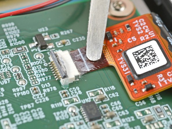
    • Apply a heated iOpener to the digitizer cable ZIF connector for 90 seconds to soften the coating.

    • Alternatively, you can use a hair dryer or a heat gun.

  32. Motherboard Disconnection (Screen), Disconnect the digitizer cable: step 32, image 1 of 3 Motherboard Disconnection (Screen), Disconnect the digitizer cable: step 32, image 2 of 3 Motherboard Disconnection (Screen), Disconnect the digitizer cable: step 32, image 3 of 3
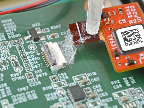
    • Grip the digitizer cable close to the head and pull it away from its ZIF connector slowly and steadily to separate the coating.

    • If the coating feels stubborn, reheat the connector and try again.

    • Keep pulling on the cable until it comes completely out of its socket.

    • During reassembly:

    • Inspect the head of the cable and the ZIF connector for any remaining coating that could prevent a good connection.

    • Peel off the coating—heating the cable and the ZIF connector when the coating becomes too brittle.

    • It doesn't have to look pretty! You just need to remove enough coating to have the cable sit properly in its connector.

  33. Motherboard Disconnection (Screen), Unlock the display ZIF connector: step 33, image 1 of 3 Motherboard Disconnection (Screen), Unlock the display ZIF connector: step 33, image 2 of 3 Motherboard Disconnection (Screen), Unlock the display ZIF connector: step 33, image 3 of 3
    • There are surface-mounted components next to the display ZIF connector. Follow the instructions carefully to avoid dislodging them.

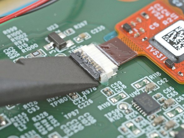
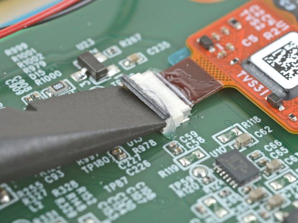
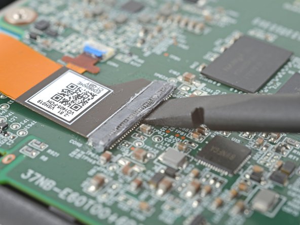
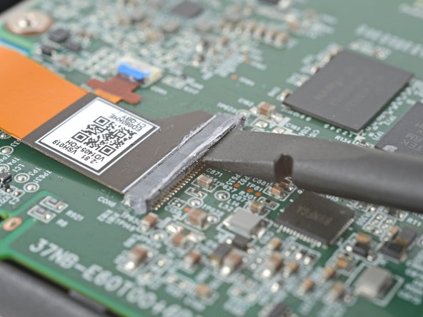
    • Insert the flat end of a spudger under the right side of the ZIF connector's black locking tab.

    • Lift up the locking tab with the spudger to unlock it.

    • The locking tab should be nearly vertical when unlocked. If not, gently push the tab forward to compress the gel and completely unlock the tab.

  34. Motherboard Disconnection (Screen), Soften the display connector coating: step 34, image 1 of 1
    • Apply a heated iOpener and lay it on the display connector for 90 seconds to soften the coating.

    • Alternatively, you can use a hair dryer or a heat gun.

  35. Motherboard Disconnection (Screen), Disconnect the display cable: step 35, image 1 of 2 Motherboard Disconnection (Screen), Disconnect the display cable: step 35, image 2 of 2
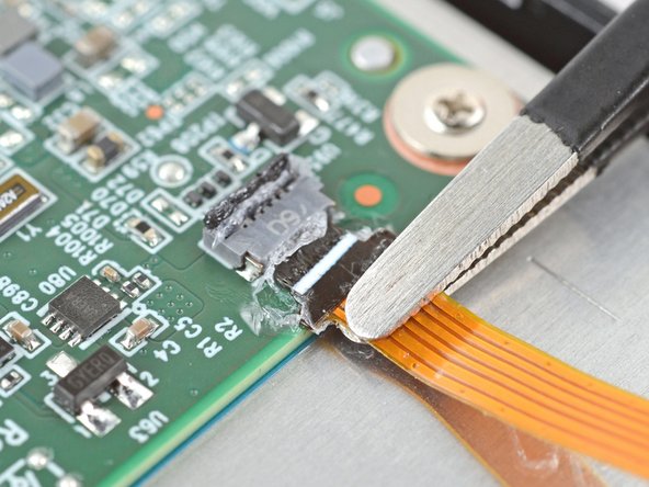
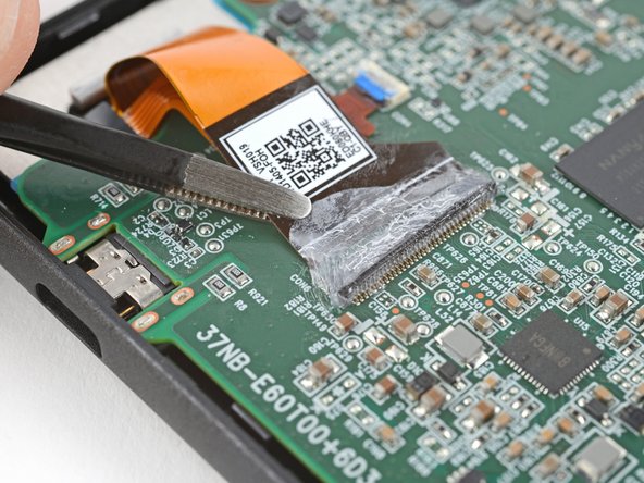
    • Use blunt nose tweezers to grip the corner of the display cable closest to the charging port.

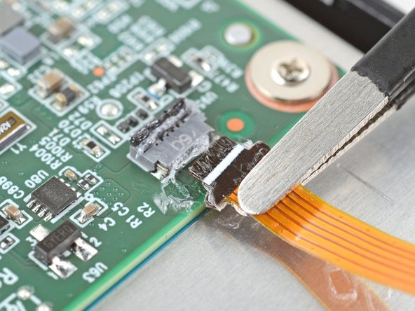
    • Pull the cable away from the ZIF connector slowly and steadily at a level angle to separate the coating at the corner.

    • If you're having trouble, try rocking the cable side-to-side while pulling.

    • Gripping the tweezers closer to the tip can help with getting a tighter hold on the cable.

  36. Motherboard Disconnection (Screen): step 36, image 1 of 2 Motherboard Disconnection (Screen): step 36, image 2 of 2
    • Repeat the previous step for the other corner until the the cable comes completely out of its socket.

  37. Motherboard Disconnection (Screen): step 37, image 1 of 3 Motherboard Disconnection (Screen): step 37, image 2 of 3 Motherboard Disconnection (Screen): step 37, image 3 of 3
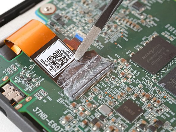
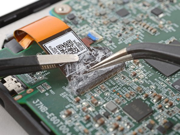
    • Lift up the display cable and peel off any remaining coating holding it to the motherboard.

    • During reassembly:

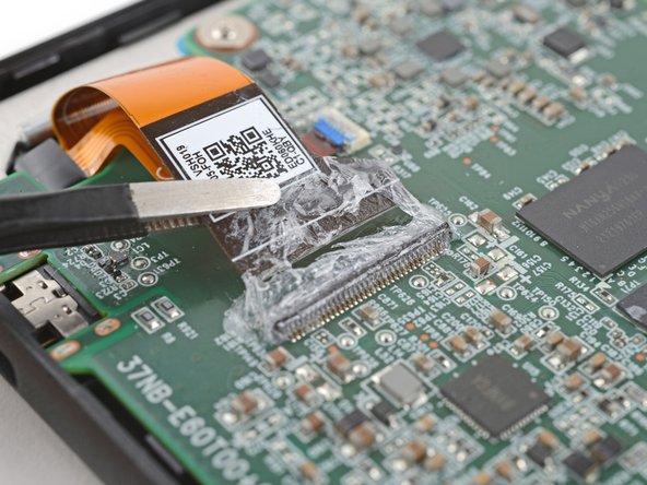
    • Inspect the ends of the cable and the ZIF connectors for any remaining coating that could prevent a good connection.

    • Peel off the coating—heating the cable and the ZIF connector when the coating becomes too brittle.

    • It doesn't have to look pretty! You just need to remove enough coating to have the cable sit properly in the connector.

  38. Motherboard Disconnection (Screen), Unlock the backlight cable ZIF connector: step 38, image 1 of 3 Motherboard Disconnection (Screen), Unlock the backlight cable ZIF connector: step 38, image 2 of 3 Motherboard Disconnection (Screen), Unlock the backlight cable ZIF connector: step 38, image 3 of 3
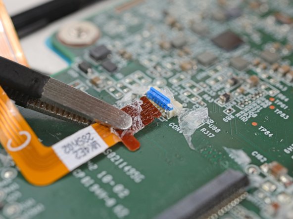
    • Lift the display cable out of the way of the backlight cable underneath.

    • Use the point of a spudger to lift up the blue locking tab on the backlight cable ZIF connector.

    • The locking tab should be nearly vertical when unlocked. If not, gently push the tab forward to compress the gel and completely unlock the tab.

  39. Motherboard Disconnection (Screen), Soften the backlight connector coating: step 39, image 1 of 1
    • Apply a heated iOpener and lay it on the backlight connector for 90 seconds to soften the coating.

    • Alternatively, you can use a hair dryer or a heat gun.

  40. Motherboard Disconnection (Screen), Disconnect the backlight cable: step 40, image 1 of 2 Motherboard Disconnection (Screen), Disconnect the backlight cable: step 40, image 2 of 2
    • Use blunt nose tweezers to grip the cable close to the head and pull it away from its ZIF connector slowly and steadily to separate the coating.

    • If the coating feels stubborn, reheat the connector and try again.

    • Keep pulling on the cable until it comes completely out of its socket.

    • During reassembly:

    • Inspect the head of the cable and the ZIF connector for any remaining coating that could prevent a good connection.

    • Peel off the coating—heating the cable and the ZIF connector when the coating becomes too brittle.

    • It doesn't have to look pretty! You just need to remove enough coating to have the cable sit properly in its connector.

Conclusion

To reassemble your device, follow these instructions in reverse order.

Alex Diaz-Kokaisl

Member since: 01/16/22

124,319 Reputation

581 Guides authored

Team

iFixit Member of iFixit

Staff

135 Members

17,218 Guides authored

0 Comments

Add Comment

View Statistics:

Past 24 Hours: 0

Past 7 Days: 3

Past 30 Days: 18

All Time: 40