Introduction
MacBook Pro won't read disks? Use this guide to replace a broken optical drive.
What you need
-
-
Remove the following ten screws securing the lower case to the upper case:
-
Seven 3 mm Phillips screws.
-
Three 13.5 mm Phillips screws.
-
-
-
Remove the two 5-Point Pentalobe screws along the top edge of the battery.
-
-
-
-
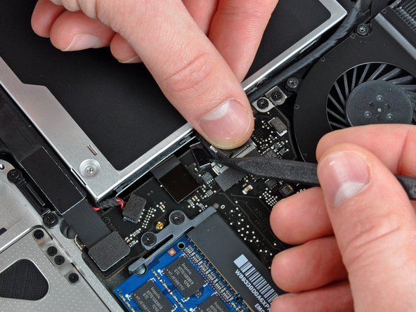
Hold the end of the cable retainer down with one finger while you use the tip of a spudger to slightly lift the other end and rotate it away from the camera cable connector.
-
-
-
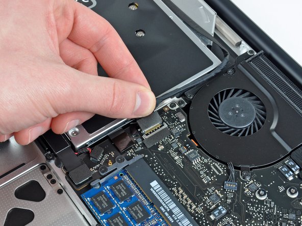
Remove the optical drive cable by pulling it straight away from the optical drive.
-
-
-
Remove the two black Phillips #0 screws securing the small metal mounting bracket. Transfer this bracket to your new optical drive or hard drive enclosure.
-


To reassemble your device, follow these instructions in reverse order.
To reassemble your device, follow these instructions in reverse order.
Cancel: I did not complete this guide.
49 other people completed this guide.

4 Comments
My replacement drive had screwholes in slightly different places and a different connector ribbon, but I was able to successfully swap the drive top plate, inner side screw bracket and connector ribbon with the ones from the existing drive.
Replaced the drive. DVD inserts. Drive works. But the DVD won't eject. Seems like the slot in the case and the drive don't align. Any Ideas?