Introduction
Use this guide to replace the metal vibrate/ring switch cover. This guide is not for the electronic portion of the vibrate/ring switch.
What you need
-
-
Power off your iPhone before beginning disassembly.
-
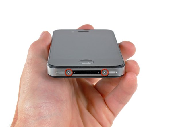
Your iPhone 4 rear cover may have either two #000 Phillips screws or Apple's 5-Point "Pentalobe" screws (second image). Check which screws you have, and ensure you also have the correct screwdriver in order to remove them.
-
Remove the two 3.6 mm Pentalobe or Phillips #000 screws next to the dock connector.
-
-
-
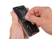
Remove the single 2.5 mm Phillips screw securing the battery connector to the logic board.
-
-
-
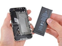
Use the clear plastic pull tab to gently lift the battery out of the iPhone.
-
If there's any alcohol solution remaining in the phone, carefully wipe it off or allow it to air dry before installing your new battery.
-
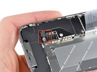
Before reconnecting the battery connector, be sure the contact clip (shown in red) is properly positioned next to the battery connector.
-
-
-
Use a SIM card eject tool or a paperclip to eject the SIM card and its holder.
-
Remove the SIM card and its holder.
-
-
-
-
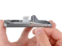
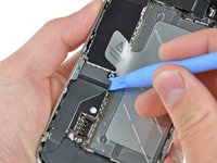
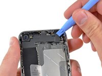
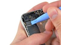
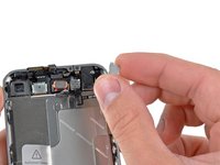
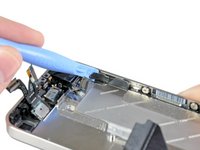
Use an iPod opening tool to slightly lift the top edge of the Wi-Fi antenna away from the logic board.
-
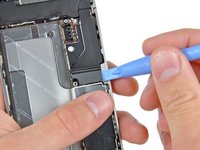
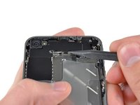
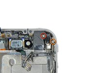
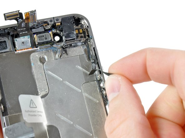
Use the tip of a spudger to pull the Wi-Fi retaining clips away from the inner frame.
-
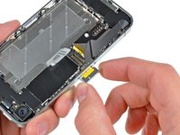
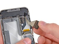
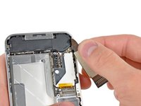
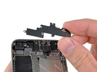
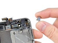
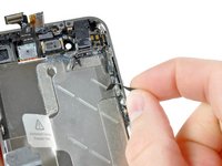
Remove the Wi-Fi antenna from the iPhone. Make sure you don't lose the metal clips on the top of the cover where the 4.8mm screw attaches or the 4.8mm screw. That's the primary reason for abnormal Wi-Fi performance after the reassembly.
-
-
-
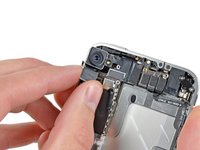
Use the edge of a plastic opening tool to gently pry the following connectors up and out of their sockets on the logic board:
-
Digitizer cable (pry from bottom)
-
LCD cable (pry from bottom)
-
Headphone jack/volume button cable (pry from top)
-
Top Microphone/sleep button cable (pry from top)
-
Front camera cable (pry from top)
-
-
-
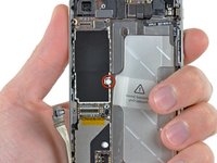
Use the edge of a plastic opening tool to lift the thin steel front camera retainer off the front camera.
-
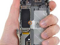
Remove the front camera retainer.
-
-
-
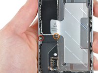
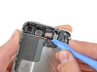
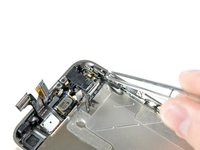
Remove the following two screws securing the vibrator to the inner frame:
-
One 6 mm Phillips screw
-
One 1.4 mm Phillips screw
-
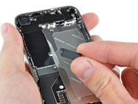
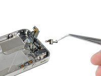
Remove the vibrator from the inner case.
-
-
-
Use the edge of a plastic opening tool to peel the electronic portion of the silent switch off its metal bracket.
-
Transfer the bracket to the new silent switch.
-
Repeat this procedure to peel the metal volume button bracket off the electronic portion of the volume buttons.
-
Transfer the volume button bracket to the new volume buttons.
-


To reassemble your device, follow these instructions in reverse order.
Cancel: I did not complete this guide.
58 other people completed this guide.
Attached Documents

3 Guide Comments
It should be added that before you perform ANY repairs to the iPhone 4, power it off and eject the SIM card FIRST. Then enjoy the rest of the repair! :)
But in step 7 you have a picture and saying to remove the chip tray, don't you think ?!