Introduction
Use this guide to replace a damaged home button to regain use of your iPhone.
What you need
Video Overview
-
-
Power off your iPhone before beginning disassembly.
-
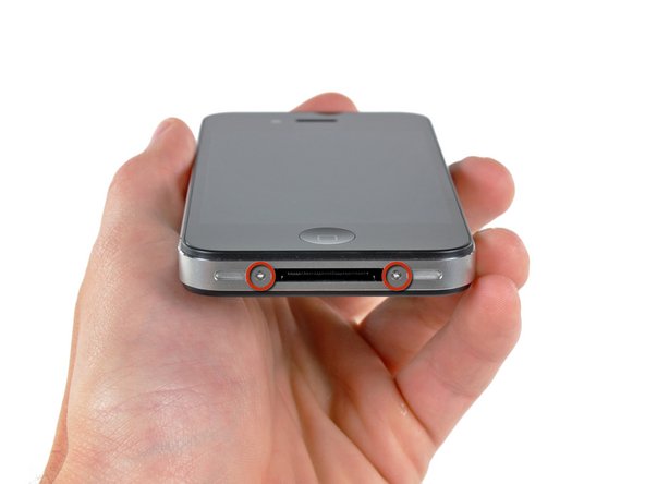
Your iPhone 4 rear cover may have either two #000 Phillips screws or Apple's 5-Point "Pentalobe" screws (second image). Check which screws you have, and ensure you also have the correct screwdriver in order to remove them.
-
Remove the two 3.6 mm Pentalobe or Phillips #000 screws next to the dock connector.
-
-
-
Remove the single 2.5 mm Phillips screw securing the battery connector to the logic board.
-
-
-
Use the clear plastic pull tab to gently lift the battery out of the iPhone.
-
If there's any alcohol solution remaining in the phone, carefully wipe it off or allow it to air dry before installing your new battery.
-
Before reconnecting the battery connector, be sure the contact clip (shown in red) is properly positioned next to the battery connector.
-
-
-
Use a SIM card eject tool or a paperclip to eject the SIM card and its holder.
-
Remove the SIM card and its holder.
-
-
-
-
Use an iPod opening tool to slightly lift the top edge of the Wi-Fi antenna away from the logic board.
-
Use the tip of a spudger to pull the Wi-Fi retaining clips away from the inner frame.
-
Remove the Wi-Fi antenna from the iPhone. Make sure you don't lose the metal clips on the top of the cover where the 4.8mm screw attaches or the 4.8mm screw. That's the primary reason for abnormal Wi-Fi performance after the reassembly.
-
-
-
Use the edge of a plastic opening tool to gently pry the following connectors up and out of their sockets on the logic board:
-
Digitizer cable (pry from bottom)
-
LCD cable (pry from bottom)
-
Headphone jack/volume button cable (pry from top)
-
Top Microphone/sleep button cable (pry from top)
-
Front camera cable (pry from top)
-
-
-
Remove the single 2.4 mm Phillips screw securing the speaker enclosure to the side of the inner frame.
-
-
-
Remove the following two screws securing the vibrator to the inner frame:
-
One 6 mm Phillips
-
One 1.4 mm Phillips
-
Remove the vibrator from the iPhone.
-
-
-
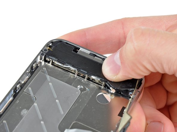
Slowly and gently lift the top edge of the front panel assembly away from the steel inner frame.
-
Continue to rotate the front panel assembly away from the steel inner frame until it slowly begins to peel off the adhesive applied below the home button area.
-
It may be easiest to insert a spudger at the top and work it around the edges, spreading gently as you go.
-
Carefully pull the lower edge of the front panel assembly away from the steel inner frame.
-
-
-
De-route the digitizer and LCD cables through the steel inner frame, and remove the display from the iPhone.
-
When the front panel has been correctly installed, both the LCD and digitizer cables should be immediately next to one another and should be the same length, as shown in the second photo.
-
During reassembly, do not touch the metallic area at the base of the LCD data cable, as this can cause problems with the LCD. If you do touch it accidentally, clean it gently with an alcohol wipe before continuing.
-
-
-
Use the edge of an iPod opening tool or your fingernail to lift the home button ribbon cable retainer.
-


To reassemble your device, follow these instructions in reverse order.
To reassemble your device, follow these instructions in reverse order.
Cancel: I did not complete this guide.
1675 other people completed this guide.
Attached Documents

85 Comments
Utter and complete failure. Followed the directions to a 'T' to replace my home button. Home button works now. Digitizer and screen now only work periodically. Degreased the connections with windex and it only made it worse.
I followed this guide slowly and carefully and it worked perfectly, just used tissue instead of windex and everything is fine, saved me £139 that apple wanted to charge me :)