Introduction
Use this guide to replace your iPad's LCD.
What you need
-
-
If your display glass is cracked, keep further breakage contained and prevent bodily harm during your repair by taping the glass.
-
Lay overlapping strips of clear packing tape over the iPad's display until the whole face is covered.
-
Do your best to follow the rest of the guide as described. However, once the glass is broken, it will likely continue to crack as you work, and you may need to use a metal prying tool to scoop the glass out.
-
-
-
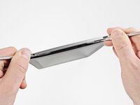
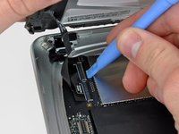
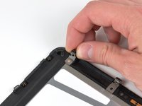
Insert a metal spudger between the top edge of the display assembly and the rear panel assembly.
-
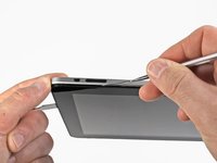
Rotate the spudger away from you to release the tabs along the top edge of the display.
-
Insert a second metal spudger between the top edge of the display assembly and the rear panel assembly to keep the tabs from snapping back into place.
-
-
-
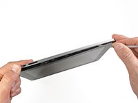
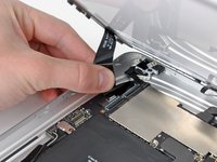
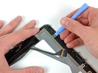
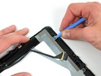
With one spudger, work your way along the right edge of the iPad.
-
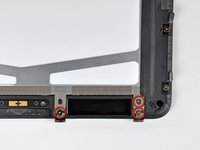
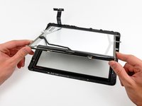
The front panel is held to the aluminum back by metal clips on the top, bottom, and left sides. The right side has plastic tabs which slide into recesses in the backplate.
-
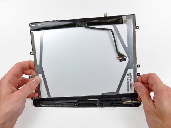
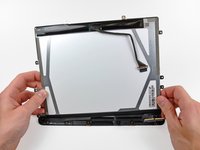
Once the clips are released, lift the left side of the front panel up and slide it to the left to clear the tabs from the aluminum backplate.
-
-
-
-
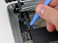
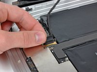
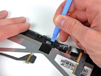
Use the edge of a plastic opening tool to carefully pry the ambient light sensor board off the adhesive securing it to the display frame.
-
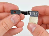
Once you've gained enough clearance, peel the ambient light sensor off the LCD.
-
-
-
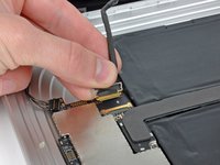
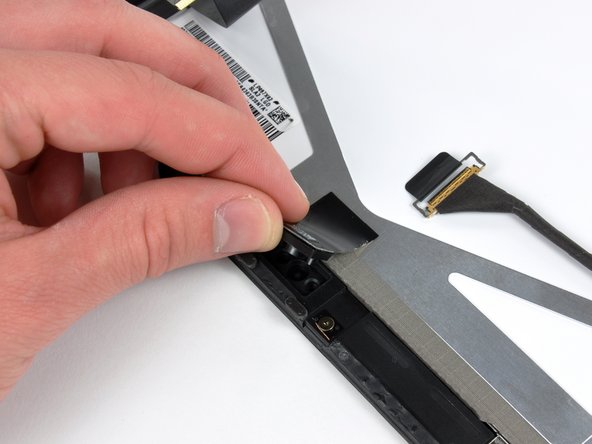
While holding the digitizer cable down, carefully peel back the piece of tape connecting the digitizer cable to the display frame.
-


To reassemble your device, follow these instructions in reverse order.
Cancel: I did not complete this guide.
79 other people completed this guide.

4 Guide Comments
So what if ive snapped off one of the retaining flaps? Ive seen in the past when ive snapped them off before i could just plug it in, slap on some kapton tape and it was fine. This time i cant get the bottom of the digitizer to work on new glass. I put on the old glass and the bottom works just fine. the bottom flap is the one that broke, but why would the old glass work just fine, but the new glass does nothing on the bottom half?
Just replaced my lcd using this guide. Not easy, but doable. Took about an hour and a half. broke about half of the clips that hold the assembly in, but moved the remaining ones around so that it is secure. I recommend buying replacement clips if you aren't comfortable with that. Also, this guide says to use a Torx T5 screwdriver. Other sites say T4. It is most definitely T5. I bought the wrong one first and had to get a new one. Home Depot has an 8 in 1 Torx tool for 6 bucks that is great. Thank you iFixit for saving me hundreds that I would have spent on a new iPad!
Don't worry about buying more replacment clips -- if you still have them on the left edge, not having the clips on the top and bottom isn't noticeable.
Styg -
When reassembling at the last step (inserting the screen assembly into the back cover), do NOT simply do the reverse of what you did to take it out. Instead, insert the right edge first (with the plastic tabs). The metal tabs on the left edge (and top and bottom edges if you have any left) are flexible, so it is very easy to snap the left edge of the screen into the back cover AFTER the right edge is in place. If you put the left edge in first, you'll have a much tougher time trying to get the plastic tabs on the right edge into back cover.