Installing iPad Wi-Fi Headphone Jack/Microphone Assembly

Replace a blown out microphone or a broken headphone jack on your iPad Wi-Fi.

  • Add Note x
  • x 4

Use this guide to replace your iPad's Headphone Jack/Microphone Assembly.

first image
thumb image 1
thumb image 2

Add Note Edit Step 1 — Display Assembly  ¶ 

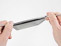
  • Insert a metal spudger between the top edge of the display assembly and the rear panel assembly.

  • Rotate the spudger away from you to release the tabs along the top edge of the display.

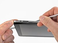
  • Insert a second metal spudger between the top edge of the display assembly and the rear panel assembly to keep the tabs from snapping back into place.

first image
thumb image 1
thumb image 2

Add Note Edit Step 2  ¶ 

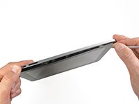
  • With one spudger, work your way along the right edge of the iPad.

  • The front panel is held to the aluminum back by metal clips on the top, bottom, and left sides. The right side has plastic tabs which slide into recesses in the backplate.

  • Once the clips are released, lift the left side of the front panel up and slide it to the left to clear the tabs from the aluminum backplate.

first image

Add Note Edit Step 3  ¶ 

  • Lift the display assembly away from the rear panel assembly by its bottom edge.

  • Do not attempt to remove the display at this time, as it is attached to the rear panel assembly.

first image

Add Note Edit Step 4  ¶ 

  • In the following steps, you will disconnect the three cables attaching the display assembly to the logic board. The cables are for the following components:

    • Digitizer

    • Ambient Light Sensor

    • Display Data Cable

first image
thumb image 1
thumb image 2
thumb image 3

Add Note Edit Step 5  ¶ 

  • Use the edge of a plastic opening tool to flip up the retaining flaps holding the digitizer ribbon cables in their sockets on the logic board.

  • Be sure you are flipping up the retaining flap, not the socket itself.

  • Pull the digitizer ribbon cables straight out of their sockets.

first image

Add Note Edit Step 6  ¶ 

  • Use a plastic opening tool to remove the ambient light sensor connector from its socket by gently prying upward.

first image
thumb image 1
thumb image 2

Add Note Edit Step 7  ¶ 

  • Disconnect the display data cable from the main board by flipping up the metal retainer by its black plastic pull tab.

  • Pull the cable connector away from its socket.

  • Pull the connector parallel to the face of the logic board.

first image

Add Note Edit Step 8  ¶ 

  • Remove the display assembly from the rear panel assembly.

first image

Add Note Edit Step 9 — Headphone Jack/Microphone Assembly  ¶ 

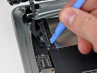
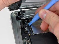
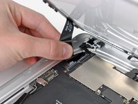
  • Use the edge of an iPod opening tool or your fingernail to flip up the ZIF cable retaining flap on the headphone jack socket.

  • Be sure you pry up on the cable retaining flap, not the socket itself.

first image

Add Note Edit Step 10  ¶ 

  • Carefully pull the headphone jack cable out of its socket on the logic board.

first image

Add Note Edit Step 11  ¶ 

  • Remove the two 2.8 mm T5 Torx screws securing the headphone jack to the rear case.

first image

Add Note Edit Step 12  ¶ 

  • Remove the headphone jack from the rear case.

  • Make sure you transfer the rubber sound channel from your old microphone to the new microphone.

  • Before reinstalling the screws, be sure the headphone jack is properly seated in the headphone jack hole cut into the top edge of the rear case.

To reassemble your device, follow these instructions in reverse order.

For more information, check out the iPad Wi-Fi device page.

Did you successfully follow this guide?

This guide has been completed 4 times.

Comments Add Note Comments are offturn on