Introduction
Use this guide to replace a broken LCD.
What you need
-
-
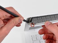
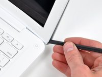
Insert the flat end of a spudger between the thin rubber strip surrounding the front display bezel and the rear display bezel.
-
Use the flat end of your spudger to carefully pry the front display bezel away from the adhesive securing it to the rear display bezel.
-
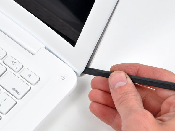
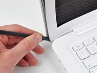
Continue prying until the front display bezel is free along the right side of the display and behind the right clutch hinge.
-
-
-
-
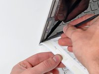
Slowly work your way across the lower edge of the front display bezel until it is free from the display assembly.
-
When you get about half way across, pry up from the other side of the front display bezel's lower edge to ease the process.
-
Remove the front display bezel from the display assembly.
-
-
-
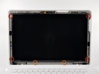
Remove following six screws securing the LCD to the rear display bezel:
-
Four 3.4 mm Phillips.
-
Two 3 mm Phillips.
-
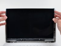
Hold the display vertically and tip it enough to grab the top edge of the LCD and rotate it slightly out of the display assembly, being careful not to break the circuitry off its lower edge.
-
-
-
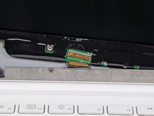
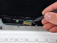
Use the tip of a spudger to flip up the thin steel retaining clip securing the display data cable to its socket on the LCD.
-
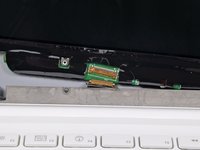
While holding the display data cable by the retaining clip, pull the LCD straight up and away from its socket.
-
Lift the LCD out of the display assembly and set it aside.
-


To reassemble your device, follow these instructions in reverse order.
Cancel: I did not complete this guide.
168 other people completed this guide.

24 Guide Comments
I thought exactly the same thing: towards the end, it gets really tricky and there should be a lot more details in the repair guide. I somehow figured out myself how to do it, but i think i wouldn't have dared to do the whole thing, if i had known how difficult it would be at the end. you need a lot of patience and sensitivity to fit the cable into the little socket.
great news.
I had a little accident to my Mac yesterday, just ordered the new LCD. I have a question though:
what is the little black cable for on the upper right? Cuz' mine teared apart...
The thin black cables that go up the right side of the screen are your Airport antenna wires and the one running up the left side goes to the iSight camera.
Hello Everyone!
I'm done with the repair. My MacBook looks beautiful with the new Anti-Glare iFixit LCD screen I love it. Getting the display data cable into the socket wasn't that bad. I could solve it in 5 minutes. But needed 4 hands :)
Everybody should try if the screen break and iFixit guys are really really helpful!! Thank you once again!!