Introduction
Save money by replacing just the LCD rather than the whole display assembly.
What you need
-
-
With the case closed, place the Unibody top-side down on a flat surface.
-
Depress the grooved side of the access door release latch enough to grab the free end. Lift the release latch until it is vertical.
-
-
-
Remove the following eight screws securing the lower case to the chassis:
-
One 3 mm Phillips screw.
-
Three 13.5 mm Phillips screws.
-
Four 3.5 mm Phillips screws.
-
-
-
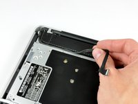
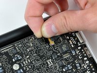
Disconnect the camera cable by pulling the male end straight away from its socket.
-
-
-
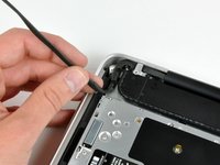
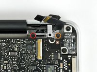
Remove the following screws securing the camera data cable and right speaker to the upper case:
-
One 9.9 mm partially threaded Phillips screw
-
One 9.6 mm threaded Phillips screw
-
One 4 mm Phillips screw
-
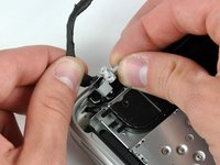
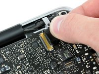
Slide the camera cable bracket out from under the subwoofer and remove it from the computer.
-
-
-
-
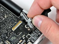
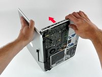
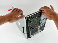
Grab the upper case with your right hand and rotate it slightly toward the top of the display so the upper display bracket clears the edge of the upper case.
-
Rotate the display slightly away from the upper case.
-
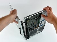
Lift the display away from the upper case, minding any brackets or cables that may get caught.
-
-
-
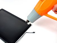
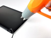
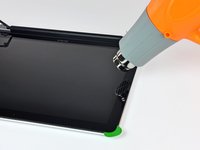
With the heat gun set to low, start by heating the outer black border near the upper right corner of the glass panel.
-
-
-
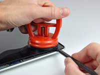
Gently lift the corner of the display glass enough to insert a spudger between it and the display assembly.
-
Use the flat end of a spudger to gently pry up the adhesive securing the front glass to the display.
-
Pry up the glass panel a few inches away from the upper right corner along the top and right edges of the display.
-
-
-
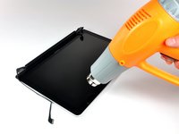
Use a heat gun to soften the adhesive under the black strip along the right side of the front glass panel.
-
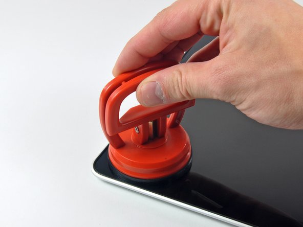
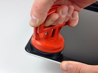
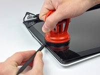
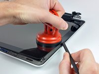
Attach a suction cup along the right side of the front glass panel.
-
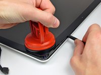
Pull up on the glass panel while you use the flat end of a spudger to separate it from the rest of the display assembly.
-
Continue working along the right edge of the front display glass until it is separated from the display.
-
-
-
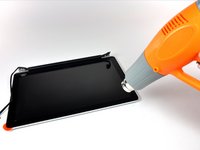
Use your heat gun to soften the adhesive under the black strip along the top edge of the glass display panel.
-
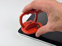
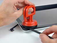
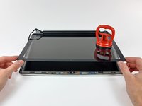
Attach a suction cup near the top edge of the glass display panel and use it to pull the glass panel up off the display.
-
Work along the top edge of the glass panel, carefully using the flat end of a spudger to separate the adhesive if necessary.
-
-
-
Use a heat gun to soften the adhesive under the black strip near the upper left corner of the glass display panel.
-
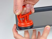
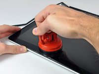
Attach a suction cup near the upper left corner of the glass display panel.
-
Pull up on the suction cup and use the flat end of a spudger to carefully pry the glass display panel out of the display assembly.
-
-
-
Use a heat gun to soften the adhesive under the black strip along the left side of the front glass panel.
-
Attach a suction cup along the left side of the front glass panel.
-
Pull up on the glass panel while you use the flat end of a spudger to separate it from the rest of the display assembly.
-
Continue working along the left edge of the front display glass until it is separated from the display.
-
-
-
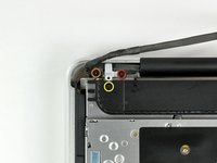
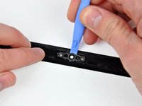
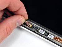
To reconnect the cable, first use the tip of a spudger to remove the piece of foam tape over the AirPort & iSight data cable ZIF socket.
-
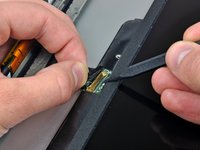
Use the tip of a spudger to flip up the ZIF cable retainer on the AirPort & iSight data cable socket.
-
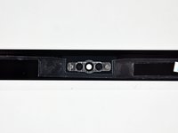
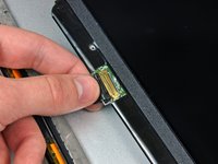
Insert the AirPort & iSight data cable into its socket on the camera board and use the tip of a spudger to snap down the ZIF cable retainer, locking the cable in place.
-
-
-
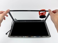
Starting at its far right end, rock the clutch cover along its long axis while pulling it away from the clutch hinge.
-
Working from right to left, carefully continue to release and lift the clutch along the lower edge of the display assembly.
-
Lift the clutch cover up off the front bezel and set it aside.
-
-
-
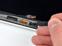
De-route the display data cable from its retaining bracket near the lower left edge of the display.
-
-
-
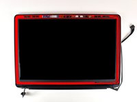
Hold the display vertically and tip it enough to grab the top edge of the LCD and rotate it slightly out of the display assembly, being careful not to break the circuitry off its lower edge.
-
Pull the LCD toward the top edge of the display to slide the circuitry along its lower edge out of the recess in the aluminum display assembly.
-


To reassemble your device, follow these instructions in reverse order.
Cancel: I did not complete this guide.
89 other people completed this guide.

16 Guide Comments
I followed the steps regarding removing the display glass, since my old one needed replacing. Unfortunately it did not come off, even with a good amount of heat from a heat gun. I felt any more heat would start to melt things. Eventually I tried prying a corner, which caused a crack, and ultimately I ended up chipping out tiny shards of glass everywhere. Eventually I got it done, but it was a royal pain. BE CAREFUL AND WEAR SAFETY GLASSES.
There are other guides for replacing the LCD on the 13" Macbook unibody without removing the whole display assembly. I tried this and had some problems when it came to reconnecting the new LCD to the LVDS. The main problem with this is that the LVDS connector cable is very short and therefore there is not a lot of room for plugging it into the LCD. After a while I decided to follow the ifixit guide and remove the display assembly. This made things very easy since I could push the LVDS cable back a little which gave me enough room for reconnecting the LVDS easily.
Removing the glass front was difficult at first. I used a cheap suction cup (not from ifixit) but the glass didn't come off at all. At some point the suction cup broke, the rubber just came off. So I used a hair dryer and a credit card to get into the lower right corner. I started by placing the credit card in the small opening between the edge of the glass and the rubber lip (at right angle). Then I carefully and patiently dug into the corner, and as soon I was in I could carefully detach the glass from its adhesive (frequently using the hairdryer). Maybe I was just lucky, but for me this worked fine.
The rest was pretty easy (except reconnecting the LVDS which was a pain at first; see my other comment). I used permanent double sided tape to put the glass back on, which seems to work just fine.
Ok I tried to remove the front glass with a hair dryer with no success. The back case became so hot I can't even hold it to pull this the suction cup...
So I borrowed a heat gun and it was very easy to remove. I was surprised. I heated until I saw steam inside the panel through the glass. I then pulled hard on one corner ands it came. After that the all glass came easily without reheating.
After the LCD panel exchange I manage to have no dust or finger tips inside and put the glass back on its old tape glu. And shazam !
The MacBook now work great again.
Thank you ifixit.
Thank you all was ok.