Installing MacBook Pro 17" Unibody Upper Case

Replace the upper case on your MacBook Pro 17" Unibody.

  • Add Note x
  • x 9

Use this guide to replace your MacBook Pro's upper case. Replacing the upper case requires removal of most components inside your computer, including the display assembly.

Sections
Tools
first image

Add Note Edit Step 1 — Lower Case  ¶ 

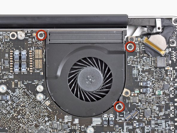
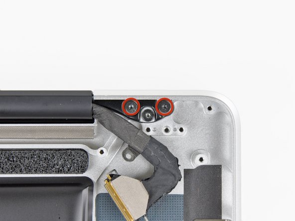
  • Remove the following ten screws securing the lower case to the upper case:

    • Three 13.5 mm Phillips screws.

    • Seven 3 mm Phillips screws.
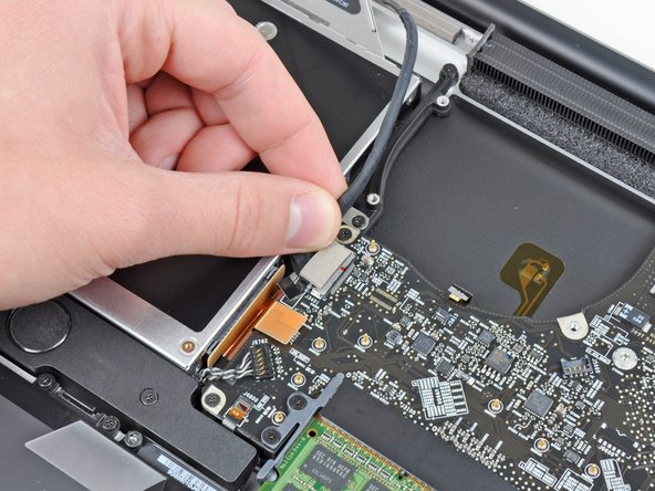
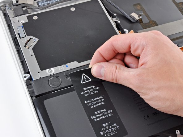
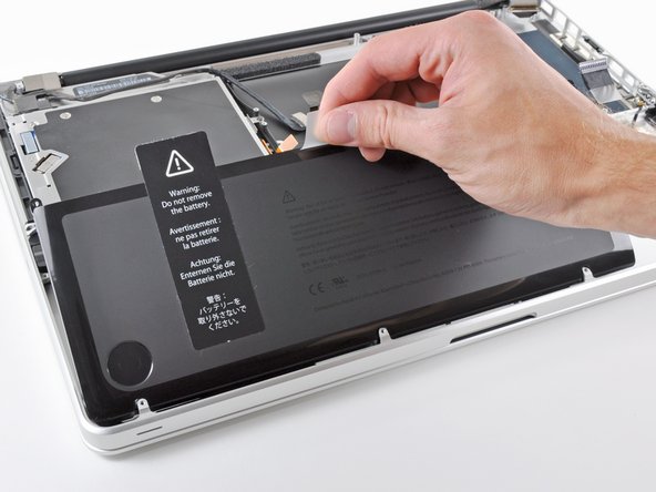
first image
thumb image 1
thumb image 2

Add Note Edit Step 2  ¶ 

  • Wedge your fingers between the lower case and the vent, and lift upward to release the clips holding the lower case to the upper case.

  • Remove the lower case.

first image
thumb image 1
thumb image 2

Add Note Edit Step 3 — Battery  ¶ 

  • Whenever working near the logic board, it is always wise to first disconnect the battery to avoid short circuits.

  • Grab the plastic tab attached to the battery connector and pull it toward the front edge of the device.

  • Pull the tab parallel to the face of the logic board.

first image
thumb image 1
thumb image 2
thumb image 3

Add Note Edit Step 4 — Right Fan  ¶ 

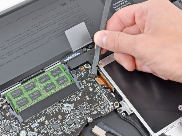
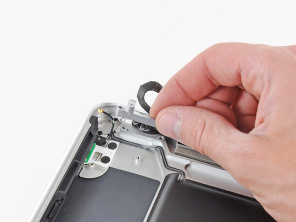
  • Use the flat end of a spudger to lift the right fan connector out of its socket on the logic board.

  • It is useful to twist the spudger axially from beneath the fan cable wires to release the connector.

  • The fan socket and the fan connector can be seen in the second and third pictures. Be careful not to break the plastic fan socket off the logic board as you use your spudger to lift the fan connector straight up and out of its socket. The layout of the logic board shown in the second picture may look slightly different than your machine but the fan socket is the same.

first image

Add Note Edit Step 5  ¶ 

  • Remove the three 3.1 mm Phillips screws securing the right fan to the logic board.

first image

Add Note Edit Step 6  ¶ 

  • Remove the right fan from the upper case, minding its cable that may get caught.

first image

Add Note Edit Step 7 — Logic Board  ¶ 

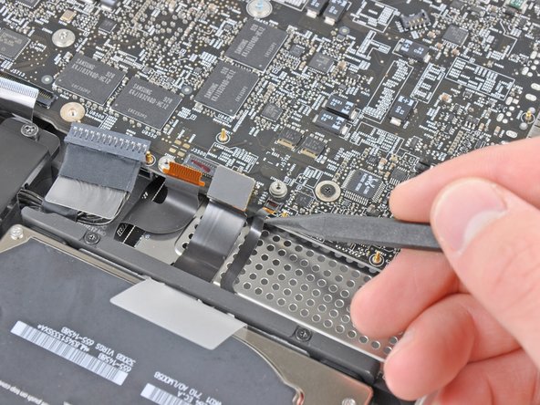
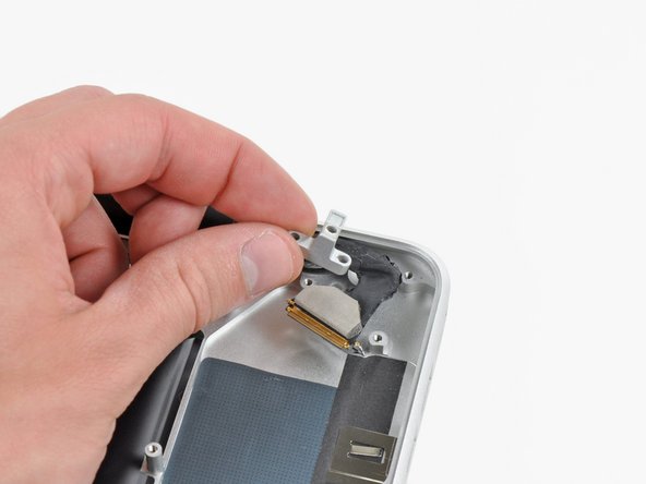
  • Use the flat end of a spudger to lift the left fan connector out of its socket on the logic board.

  • It is useful to twist the spudger axially from beneath the fan cable wires to release the connector.

first image
thumb image 1
thumb image 2

Add Note Edit Step 8  ¶ 

  • Remove the three 3.1 mm Phillips screws securing the left fan to the logic board.

  • Remove the left fan from the upper case, minding its cable that may get caught.

first image
thumb image 1
thumb image 2

Add Note Edit Step 9  ¶ 

  • Use the tip of a spudger or your fingernail to flip up the retaining flap on the keyboard backlight ribbon cable.

  • Be sure you are prying up on the retaining flap, not the socket itself.

  • Pull the keyboard backlight ribbon cable out of its socket.

first image

Add Note Edit Step 10  ¶ 

  • Before disconnecting the camera cable, a small plastic retainer stuck to the logic board must first be moved out of the way.

  • Use the tip of a spudger to push the small plastic cable retainer away from the camera cable socket for enough clearance to remove the camera cable.

first image

Add Note Edit Step 11  ¶ 

  • Pull the camera cable toward the optical drive opening to disconnect it from the logic board.

  • The camera cable socket is very fragile. Do not apply any upward force to this socket, as it may break off the logic board. Pull the camera cable parallel to the face of the logic board.

first image

Add Note Edit Step 12  ¶ 

  • Use the flat end of a spudger to pry the optical drive connector up and out of its socket on the logic board.

first image

Add Note Edit Step 13  ¶ 

  • Use the flat end of a spudger to lift the subwoofer & right speaker connector out of its socket on the logic board.

  • Pry up from beneath the wires.

first image
thumb image 1
thumb image 2

Add Note Edit Step 14  ¶ 

  • Use the tip of a spudger or your fingernail to flip up the retaining flap on the IR sensor ribbon cable socket.

  • Be sure you are prying up on the retaining flap, not the socket itself.

  • Pull the IR sensor ribbon cable out of its socket.

first image
thumb image 1
thumb image 2
thumb image 3

Add Note Edit Step 15  ¶ 

  • Remove the following four screws:

    • Two 3.5 mm Phillips screws

    • Two 1.6 mm Phillips screws

  • Remove both connector shields from the logic board.

first image

Add Note Edit Step 16  ¶ 

  • Use the flat end of a spudger to pry the trackpad connector up and out of its socket on the logic board.

first image
thumb image 1
thumb image 2

Add Note Edit Step 17  ¶ 

  • Use your fingernail to flip up the retaining flap on the keyboard ribbon cable socket.

  • Be sure you are prying up on the retaining flap, not the socket itself.

  • Pull the keyboard ribbon cable out of its socket.

first image
thumb image 1
thumb image 2

Add Note Edit Step 18  ¶ 

  • Use your fingernail to flip up the retaining flap on the express card cage ribbon cable socket.

  • Be sure you are prying up on the retaining flap, not the socket itself.

  • Pull the express card cage ribbon cable out of its socket.

first image

Add Note Edit Step 19  ¶ 

  • Use the flat end of a spudger to lift the hard drive cable connector up and out of its socket on the logic board.

first image
thumb image 1
thumb image 2

Add Note Edit Step 20  ¶ 

  • Use the tip of a spudger or your fingernail to flip up the retaining flap on the battery indicator cable socket.

  • Be sure you are prying up on the retaining flap, not the socket itself.

  • Pull the battery indicator ribbon cable out of its socket.

first image
thumb image 1
thumb image 2
thumb image 3

Add Note Edit Step 21  ¶ 

  • Lift the black plastic flap attached to the display data cable retainer and rotate it toward the DC-In side of the MacBook.

  • Pull the display data cable out of its socket.

  • The display data cable socket is very fragile. Do not lift the connector upward as you disconnect it, as the socket may break off the logic board. Pull the cable parallel to the face of the logic board.

first image

Add Note Edit Step 22  ¶ 

  • Remove the following eight screws securing the logic board and DC-In board to the upper case:

    • Six 3.2 mm Phillips screws

    • Two 7.6 mm Phillips screws

first image
thumb image 1
thumb image 2

Add Note Edit Step 23  ¶ 

  • Handle the logic board by its edges only.

  • Lift the logic board from the side nearest the optical drive and lift it away from the upper case.

  • Carefully pull the ports and DC-In board away from the side of the upper case and remove the logic board, minding any cables that may get caught.

first image
thumb image 1
thumb image 2

Add Note Edit Step 24 — Express Card Cage  ¶ 

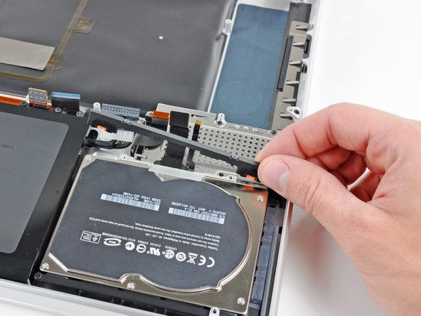
  • Remove the two Phillips screws securing the hard drive bracket to the upper case.

  • Both screws are captive to the hard drive bracket.

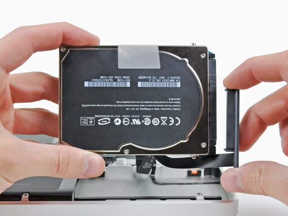
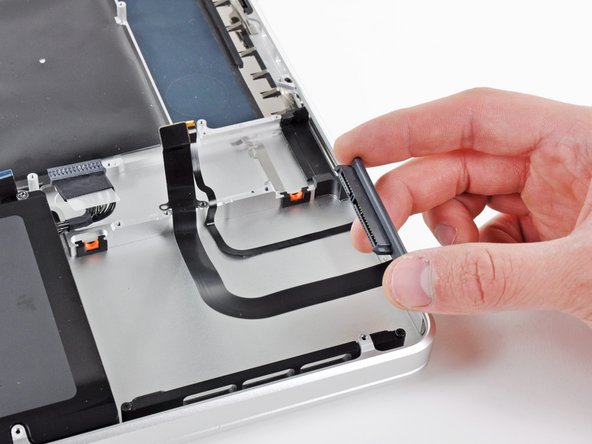
  • Remove the hard drive bracket from the upper case.

first image

Add Note Edit Step 25  ¶ 

  • Peel the hard drive and battery indicator cables off the adhesive securing them to the express card cage.

first image

Add Note Edit Step 26  ¶ 

  • Remove the following five screws securing the express card cage to the upper case:

    • Three 2 mm Phillips screws

    • Two 4 mm Phillips screws

first image

Add Note Edit Step 27  ¶ 

  • Remove the express card cage from the upper case.

first image

Add Note Edit Step 28 — Upper Case  ¶ 

  • Using its attached pull tab, lift the hard drive out of the upper case.

  • Do not try to completely remove the hard drive just yet! The hard drive cable is still attached to the upper case.

first image
thumb image 1
thumb image 2

Add Note Edit Step 29  ¶ 

  • Pull the hard drive cable connector away from the body of the hard drive.

  • Remove the hard drive from the upper case and set it aside.

first image
thumb image 1
thumb image 2

Add Note Edit Step 30  ¶ 

  • Remove the two 2.2 mm Phillips screws securing the hard drive cable to the upper case.

  • Remove the hard drive cable from the upper case.

first image
thumb image 1
thumb image 2

Add Note Edit Step 31  ¶ 

  • Remove the two 10 mm Phillips screws securing the front hard drive bracket to the upper case.

  • Remove the front hard drive bracket.

first image
thumb image 1
thumb image 2

Add Note Edit Step 32  ¶ 

  • Use an iPod opening tool or another soft thin-edged tool to carefully lift up a corner of the "Warning: Do not remove the battery" sticker off the right speaker/subwoofer enclosure.

  • Peel the sticker off the right speaker/subwoofer enclosure.

  • It is not necessary to peel the sticker off the battery.

first image
thumb image 1
thumb image 2

Add Note Edit Step 33  ¶ 

  • Remove the three 6.5 mm Y1 Tri-wing screws securing the battery to the upper case.

  • Using its attached pull tab, lift the battery out of the upper case.

first image

Add Note Edit Step 34  ¶ 

  • Carefully disconnect the Bluetooth cable from the Bluetooth board.

  • Pull the cable parallel to the face of the optical drive toward the port openings.

first image

Add Note Edit Step 35  ¶ 

  • Use the flat end of a spudger to peel the thin plastic cover off the top and sides of the Bluetooth board housing.

first image

Add Note Edit Step 36  ¶ 

  • Use the flat end of a spudger to pry the Bluetooth antenna connector up and off its socket on the Bluetooth board.

first image

Add Note Edit Step 37  ¶ 

  • Remove the small piece of EMI foam attached near the Bluetooth board.

first image

Add Note Edit Step 38  ¶ 

  • Remove the three 3.5 mm Phillips screws securing the optical drive to the upper case.

  • To remove the screw closest to the battery, it may be helpful to use a T6 Torx screwdriver to first remove the upper case bracket directly above it.

first image

Add Note Edit Step 39  ¶ 

  • Remove the optical drive assembly from the upper case.

first image

Add Note Edit Step 40  ¶ 

  • Remove the following three screws securing the subwoofer & right speaker to the upper case:

    • One 2.6 mm Phillips screw

    • Two 12.3 mm Phillips screws

first image

Add Note Edit Step 41  ¶ 

  • Remove the subwoofer and right speaker assembly from the upper case.

first image
thumb image 1
thumb image 2

Add Note Edit Step 42  ¶ 

  • Remove the two 7.1 mm Phillips screws securing the camera cable retainer to the upper case.

  • Remove the camera cable retainer from the upper case.

first image
thumb image 1
thumb image 2

Add Note Edit Step 43  ¶ 

  • Remove the two 7.1 mm Phillips screws securing the display data cable retainer to the upper case.

  • Remove the display data cable retainer.

first image
thumb image 1
thumb image 2

Add Note Edit Step 44  ¶ 

  • Remove the two outer 6.8 mm T6 Torx screws from each of the two display brackets (four screws total).

  • We purposely have you leave one screw attaching each display bracket to the upper case to aid in future steps.

first image

Add Note Edit Step 45  ¶ 

  • Open your MacBook Pro so the display is perpendicular to the upper case.

  • Place your opened MacBook Pro on a table as pictured.

  • While holding the display and upper case together with your left hand, remove the remaining T6 Torx screw from the lower display bracket.

first image

Add Note Edit Step 46  ¶ 

  • Be sure to hold the display and upper case together with your left hand. Failure to do so may cause the freed display/upper case to fall, potentially damaging each component.

  • Remove the last remaining T6 Torx screw securing the display to the upper case.

first image
thumb image 1
thumb image 2
thumb image 3

Add Note Edit Step 47  ¶ 

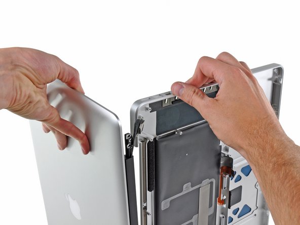
  • Grab the upper case with your right hand and rotate it slightly toward the top of the display so the upper display bracket clears the edge of the upper case.

  • Rotate the display slightly away from the upper case.

  • Lift the display up and away from the upper case, minding any brackets or cables that may get caught.

To reassemble your device, follow these instructions in reverse order.

For more information, check out the MacBook Pro 17" Unibody device page.

Did you successfully follow this guide?

This guide has been completed 9 times.

Comments Add Note Comments are offturn on