Installing MacBook Pro 15" Unibody Early 2011 Upper Case

Replace the upper case for a new keyboard, power button, trackpad, and battery indicator on your Early 2011 MacBook Pro 15" Unibody.

  • Add Note x
  • x 5

Replacing the upper case requires removal of nearly every component inside your MacBook Pro.

Sections
Tools
first image

Add Note Edit Step 1 — Lower Case  ¶ 

  • Remove the following ten screws securing the lower case to the upper case:

    • Three 13.5 mm (14.1 mm) Phillips screws.

    • Seven 3 mm Phillips screws.

first image

Add Note Edit Step 2  ¶ 

  • Using both hands, lift the lower case near the vent to pop it off two clips securing it to the upper case.

  • Remove the lower case and set it aside.

first image
thumb image 1
thumb image 2

Add Note Edit Step 3 — Battery Connector  ¶ 

  • For certain repairs (e.g. hard drive), disconnecting the battery connector is not necessary but it prevents any accidental shorting of electronics on the motherboard. If you do not disconnect the battery connector, please be careful as parts of the motherboard might be electrified.

  • Use the edge of a spudger to pry the battery connector upwards from its socket on the logic board.

  • It is useful to pry upward on both short sides of the connector to "walk" it out of its socket.

first image

Add Note Edit Step 4  ¶ 

  • Bend the battery cable slightly away from its socket on the logic board so it does not accidentally connect itself while you work.

first image

Add Note Edit Step 5 — Left Fan  ¶ 

  • Remove the three 3.4 mm (3.1 mm) T6 Torx screws securing the left fan to the logic board.

first image
thumb image 1
thumb image 2
thumb image 3

Add Note Edit Step 6  ¶ 

  • Use the flat end of a spudger to disconnect the left fan connector from the logic board.

  • It is useful to twist the spudger axially from beneath the fan cable wires to release the connector.

  • The fan socket and the fan connector can be seen in the second and third pictures. Be careful not to break the plastic fan socket off the logic board as you use your spudger to lift the fan connector straight up and out of its socket. The layout of the logic board shown in the second picture may look slightly different than your machine but the fan socket is the same.

first image

Add Note Edit Step 7  ¶ 

  • Lift the left fan out of the upper case.

first image

Add Note Edit Step 8 — Logic Board  ¶ 

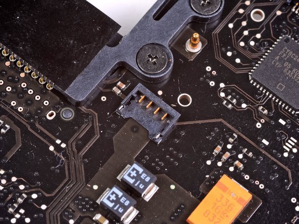
  • Use the flat end of a spudger to lift the right fan connector out of its socket on the logic board.

  • It is useful to twist the spudger axially from beneath the fan cable wires to release the connector.

first image
thumb image 1
thumb image 2

Add Note Edit Step 9  ¶ 

  • Remove the three 3.4 mm (3.1 mm) T6 Torx screws securing the right fan to the logic board.

  • Lift the right fan out of its opening in the logic board.

first image

Add Note Edit Step 10  ¶ 

  • Pull the camera cable out of its socket on the logic board.

  • Don't lift upward on the camera cable as you disconnect it. Pulling upward on the cable may damage both the cable and the logic board. Pull the cable parellel to the face of the logic board.

first image

Add Note Edit Step 11  ¶ 

  • Use the flat end of a spudger to pry the AirPort/Bluetooth connector up from its socket on the logic board.

first image

Add Note Edit Step 12  ¶ 

  • Use the flat end of a spudger to lift the optical drive connector out of its socket on the logic board.

first image

Add Note Edit Step 13  ¶ 

  • Disconnect the hard drive/IR sensor cable from its socket on the logic board by lifting up from beneath its connector.

first image

Add Note Edit Step 14  ¶ 

  • Use the flat end of a spudger to lift the subwoofer/right speaker connector out of its socket on the logic board.

  • Pry up from beneath the wires.

first image
thumb image 1
thumb image 2

Add Note Edit Step 15  ¶ 

  • Remove the two 1.5 mm ( 1.2 mm ) Phillips screws securing the keyboard/trackpad cover to the logic board.

  • Lift the cover off the logic board and set it aside.

first image

Add Note Edit Step 16  ¶ 

  • Use the flat end of a spudger to pry the trackpad connector up and out of its socket on the logic board.

first image
thumb image 1
thumb image 2

Add Note Edit Step 17  ¶ 

  • Use your fingernail to flip up the retaining flap on the keyboard ribbon cable ZIF socket.

  • Be sure you are prying up on the hinged retaining flap, not the socket itself.

  • Use the tip of a spudger to pull the keyboard ribbon cable out of its socket.

first image

Add Note Edit Step 18  ¶ 

  • Use the flat end of a spudger to lift the battery indicator connector up and out of its socket on the logic board.

first image
thumb image 1
thumb image 2

Add Note Edit Step 19  ¶ 

  • Grab the plastic pull tab secured to the display data cable lock and rotate it toward the DC-In side of the computer.

  • Pull the display data cable straight out of its socket on the logic board.

  • Do not lift up on the display data cable, as its socket is very fragile. Pull the cable parallel to the face of the logic board.

first image
thumb image 1
thumb image 2

Add Note Edit Step 20  ¶ 

  • Use the tip of a spudger to flip up the retaining flap on the keyboard backlight ribbon cable ZIF socket.

  • Be sure you are flipping up the hinged retaining flap, not the socket itself.

  • Pull the keyboard backlight ribbon cable out of its socket.

first image

Add Note Edit Step 21  ¶ 

  • Remove the following nine screws:

    • Seven 3.4 mm ( 3.1 mm) T6 Torx screws on the logic board

    • Two 8 mm T6 Torx screws on the DC-In board

first image
thumb image 1
thumb image 2
thumb image 3

Add Note Edit Step 22  ¶ 

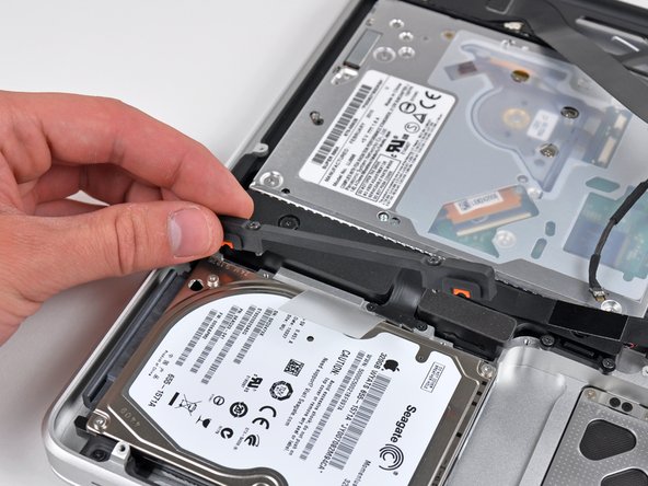
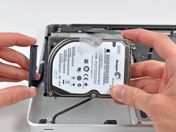
  • Carefully lift the logic board assembly from its left side and work it out of the upper case, minding the optical drive cable and the I/O ports that may get caught during removal.

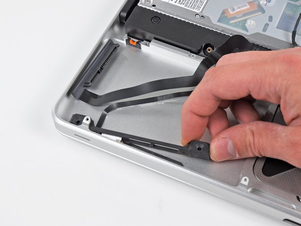
  • If necessary, use the flat end of a spudger to separate the microphone from the upper case.

  • Pull the I/O port side of the logic board away from the side of the upper case and remove the logic board assembly.

first image

Add Note Edit Step 23 — Upper Case  ¶ 

  • Remove the two 7.5 mm ( 7.2 mm )Tri-wing screws securing the battery to the upper case.

first image

Add Note Edit Step 24  ¶ 

  • Carefully peel the battery warning label off the upper case between the battery and the optical drive to reveal an additional Tri-wing screw.

  • Remove the last 7.5 mm ( 7.2 mm ) Tri-wing screw securing the battery to the upper case.

  • Do not remove the label from the battery.

first image

Add Note Edit Step 25  ¶ 

  • Use the attached plastic pull tab to remove the battery from the upper case.

first image
thumb image 1
thumb image 2

Add Note Edit Step 26  ¶ 

  • Remove the two Phillips screws securing the hard drive bracket to the upper case.

  • These screws are captive in the hard drive bracket.

  • Remove the hard drive bracket from the upper case.

first image

Add Note Edit Step 27  ¶ 

  • Using its attached pull tab, lift the hard drive out of the upper case.

  • Don't try to completely remove it yet, as it is still connected to the hard drive cable.

first image
thumb image 1
thumb image 2

Add Note Edit Step 28  ¶ 

  • Pull the hard drive connector out of its socket on the hard drive.

  • Pull on the connector, not the cable itself.

  • Remove the hard drive and set it aside.

first image

Add Note Edit Step 29  ¶ 

  • Remove the following four screws securing the hard drive/IR sensor cable to the upper case:

    • Two 2.5 mm ( 2.9 mm ) Phillips screws

    • Two 10 mm ( 9.6 mm ) Phillips screws

first image
thumb image 1
thumb image 2

Add Note Edit Step 30  ¶ 

  • Carefully peel the IR sensor cable off the adhesive securing it to the upper case.

  • Pull the hard drive bracket/IR sensor housing away from the side of the upper case.

  • Remove the hard drive/IR sensor cable from the upper case.

first image
thumb image 1
thumb image 2

Add Note Edit Step 31  ¶ 

  • Use the tip of a spudger to pry the four antenna connectors up from their sockets on the AirPort/Bluetooth board.

first image
thumb image 1
thumb image 2

Add Note Edit Step 32  ¶ 

  • De-route all four antenna cables from their channels in the AirPort/Bluetooth housing.

  • De-route the camera cable from its channel in the AirPort/Bluetooth housing.

first image
thumb image 1
thumb image 2

Add Note Edit Step 33  ¶ 

  • Remove the following two screws:

    • One 8.6 mm ( 8.4 mm ) Phillips screw

    • One 3.9 mm Phillips screw

  • Remove the AirPort/Bluetooth assembly from the upper case, minding any cables that may get caught.

first image
thumb image 1
thumb image 2

Add Note Edit Step 34  ¶ 

  • Remove the three 3.5 mm ( 3.3 mm ) T6 Torx screws securing the optical drive to the upper case.

  • Lift the optical drive near its connector and pull it away from the upper case to remove it from the computer.

first image
thumb image 1
thumb image 2

Add Note Edit Step 35  ¶ 

  • Remove the following six screws securing the subwoofer and right speaker to the upper case:

    • Two 3.2 mm ( 3.0 mm ) Phillips screws.

    • Two 12.3 mm Phillips screws.

    • One 2.5 mm Phillips screw.

    • One 8.3 mm ( 8.1 mm ) Phillips screw.

  • Lift the subwoofer and right speaker assembly out of the upper case.

first image
thumb image 1
thumb image 2

Add Note Edit Step 36  ¶ 

  • Remove the 8.6 mm Phillips screw securing the antenna/camera cable retainer to the top left portion of the upper case.

  • Remove the antenna/camera cable retainer from the upper case.

first image
thumb image 1
thumb image 2

Add Note Edit Step 37  ¶ 

  • Remove the 8.6 mm ( 7.0 mm ) Phillips screw securing the display data cable retainer to the top right portion of the upper case.

  • Remove the display data cable retainer from the upper case.

first image

Add Note Edit Step 38  ¶ 

  • Remove two of the three 6 mm T6 Torx screws securing the right side of the display to the upper case.

  • We purposely have you leave one screw attaching the display to the upper case to aid in future steps.

first image

Add Note Edit Step 39  ¶ 

  • Remove two of the three 6 mm T6 Torx screws securing the left side of the display to the upper case.

  • We purposely have you leave one screw attaching the display to the upper case to aid in future steps.

first image

Add Note Edit Step 40  ¶ 

  • Open your MacBook Pro so the display is perpendicular to the upper case.

  • Place your opened MacBook Pro on a table as pictured.

  • While holding the display and upper case together with your left hand, remove the remaining T6 Torx screw from the upper display bracket.

first image

Add Note Edit Step 41  ¶ 

  • Be sure to hold the display and upper case together with your left hand. Failure to do so may cause the freed display/upper case to fall, potentially damaging each component.

  • Remove the last remaining T6 Torx screw securing the display to the upper case.

first image
thumb image 1
thumb image 2
thumb image 3

Add Note Edit Step 42  ¶ 

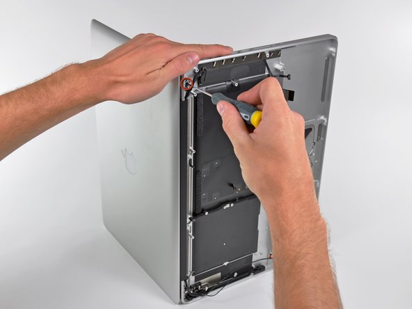
  • Grab the upper case with your right hand and rotate it slightly toward the top of the display so the upper display bracket clears the edge of the upper case.

  • Rotate the display slightly away from the upper case.

  • Lift the display up and away from the upper case, minding any brackets or cables that may get caught.

To reassemble your device, follow these instructions in reverse order.

For more information, check out the MacBook Pro 15" Unibody Early 2011 device page.

Did you successfully follow this guide?

This guide has been completed 5 times.

Comments Add Note Comments are offturn on