Introduction
Accessing the RAM requires the removal of the internal frame.
What you need
-
-
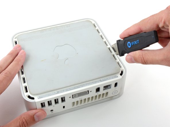
Power down your Mac mini, disconnect all of the cables, and flip it over.
-
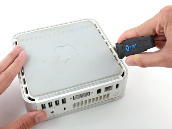
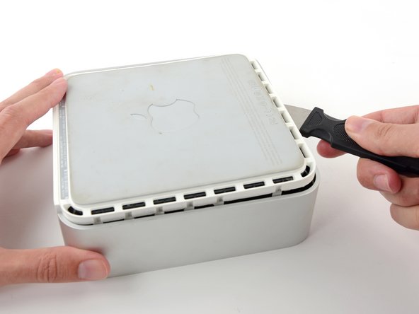
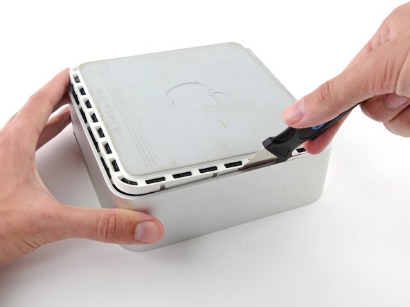
Insert the Jimmy into the crack between the aluminum top housing and the plastic lower housing.
-
The Jimmy should reach a stop about 3/8" down.
-
-
-
-
We will first remove the AirPort antenna, located in the lower left corner of this picture.
-
-
-
Simultaneously pull the tabs on each side of the RAM chip away from the center of the chip. These tabs lock the chip in place and releasing them will cause the chip to "pop" up.
-
Pull the RAM chip directly out from its connector.
-


To reassemble your device, follow these instructions in reverse order.
To reassemble your device, follow these instructions in reverse order.
Cancel: I did not complete this guide.
398 other people completed this guide.

8 Comments
Well done! Easy to follow and thorough! Took me 10 minutes start to finish!
You probably need to install Mac Mini EFI firmware update 1.2:
Wife has the Late 2009 Macmini (MM) originally with 2GB. We upgraded to 4GB a couple of years ago, and it has been running very slow with Yosemite (10.10.5) for far too long.
Ordered the 8GB upgrade kit and set for 2 day delivery. Bummer it came in 1 day via UPS. Thanks for the surprise iFixit. The tools were unnecessary for me (as I have most), but they are totally outstanding and the real deal. So I decided to use them all. ;)
The upgrade took about 15 min (even for this experienced Mac repair guy). Fired it up and the MM recognized all 8GB. It doesn’t scream, however, it is probably 2-3 times faster and can handle the amazing multi-takser that is my wife; 16 Safari pages, Mac Mail, Calendar, and 7 other apps open at all the same dang time. Thanks iFixit for the absolute best in repair universe parts, service, tech commitment, and guides.
It worked!!! Love it!!! The websites installation guide was very easy to understand. However, the small screwdriver that was shipped with the kit didn’t fit the screws for step-12, almost stripping the screws. luckily, I had another small screwdriver (for glasses) that worked.
Thank you ifixit!!! Totally worth it.