
How to Fix a Solder Bridge

What you need

  1. How to Fix a Solder Bridge, How to Fix a Solder Bridge: step 1, image 1 of 1
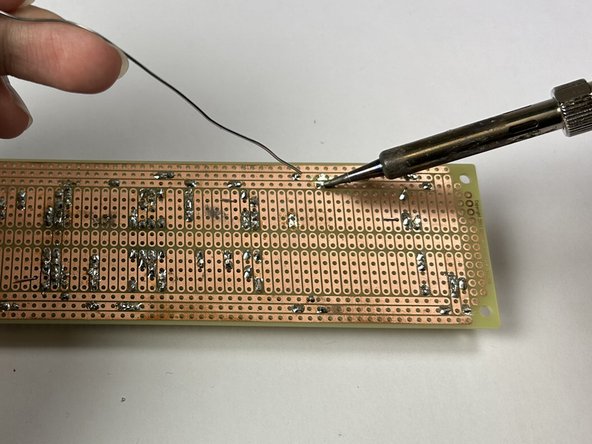
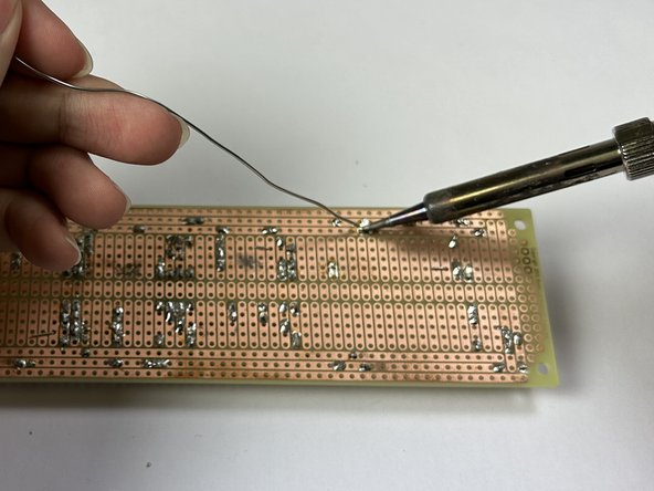
    • Set the soldering iron to 300 °C (575 °F) and wait for the iron to heat up to the desired temperature.

    • Depending on specifications of the soldering iron, it should take between 25-80 seconds for soldering iron to reach desired temperature.

    • The soldering iron tip will be very hot! Be careful when handling the soldering iron during operation.

    • Different solder may have different melting points. Refer to any documentation provided with your solder to determine the recommended temperature.

    • Avoid setting the soldering iron to very high temperatures and stay within your solder's specifications. Prolonged exposure to high temperatures can lead to component or board damage.

  2. How to Fix a Solder Bridge: step 2, image 1 of 3 How to Fix a Solder Bridge: step 2, image 2 of 3 How to Fix a Solder Bridge: step 2, image 3 of 3
    • Locate the solder bridge on the circuit board.

    • A solder bridge typically bridges two separate contact points (rails).

    • A multimeter can be used here to check for continuity (a short).

    • Apply the solder wick to the affected area.

  3. How to Fix a Solder Bridge: step 3, image 1 of 2 How to Fix a Solder Bridge: step 3, image 2 of 2
    • Place the solder wick on top of the solder bridge and heat the wick using the soldering iron by pressing on top of the affected area.

    • The solder wick will be very hot! Avoiding touching the area of the wick near the soldering iron.

    • Alternatively, use wire cutters to cut off about 2 cm (0.75") of braid. Use tweezers or needle nose pliers to place it as described above.

    • Continue to apply pressure with the soldering iron to the solder bridge until the solder is melted and absorbed by the wick.

    • A soldering flux can also be used here to aid in the desoldering process by reducing oxide films.

  4. How to Fix a Solder Bridge: step 4, image 1 of 3 How to Fix a Solder Bridge: step 4, image 2 of 3 How to Fix a Solder Bridge: step 4, image 3 of 3
    • Apply the soldering iron to the contact point.

    • Once the contact point is hot, reapply the solder to the contact point.

    • The repaired area will be very hot! Avoid touching the area being repaired.

    • Continue applying the solder to the contact point until the pin is solidly attached and the rails are separate from each other.

    • Step 7 verifies circuit continuity.

  5. How to Fix a Solder Bridge: step 5, image 1 of 3 How to Fix a Solder Bridge: step 5, image 2 of 3 How to Fix a Solder Bridge: step 5, image 3 of 3
    • The soldering iron tip will be very hot! Be careful when handling the soldering iron during its operation.

    • Hold down the dry sponge.

    • While the soldering iron is hot, use a rubbing motion across the sponge to remove excess solder off the soldering iron tip.

  6. How to Fix a Solder Bridge: step 6, image 1 of 1
    • Connect the red (positive) probe to the Voltage and Resistance Socket.

    • Connect the black (negative) probe to the Common/Ground Socket.

    • Set the multimeter knob for continuity testing. This is typically labeled with diode/audio symbols.

    • As shown in the photo, the multimeter will read "OL" if the steps above have been followed properly.

    • To ensure the functionality of the multimeter, touch the two probes together and an audible beeping sound should be emitted.

  7. How to Fix a Solder Bridge: step 7, image 1 of 1
    • Verify the circuit board does not have any current supplied to it prior to performing the next steps. If a current is present, permanent damage to the multimeter is possible!

    • Connect the black probe to the circuit board rail where one end of the solder bridge was.

    • Connect the red probe to the circuit board rail where the other end of the solder bridge was.

    • If the fix is successful, the multimeter should read "OL" on the screen, indicating an open circuit. There should be no beep, which means the rails are no longer connected.

    • If the fix was unsuccessful, the multimeter will give a numerical readout on the multimeter screen, and beep.

Conclusion

To reassemble your device, follow these instructions in reverse order.

9 other people completed this guide.

Steven

Member since: 04/19/23

253 Reputation

1 Guide authored

Team

UC Davis, Team 2-5, Morris Spring 2023 Member of UC Davis, Team 2-5, Morris Spring 2023

UCD-MORRIS-S23S2G5

3 Members

7 Guides authored

0 Comments

Add Comment

View Statistics:

Past 24 Hours: 6

Past 7 Days: 65

Past 30 Days: 397

All Time: 2,151